|
|
|
PDF ULN2003A Data sheet ( Hoja de datos )
| Número de pieza | ULN2003A | |
| Descripción | DARLINGTON TRANSISTOR ARRAYS | |
| Fabricantes | Diodes | |
| Logotipo | ||
Hay una vista previa y un enlace de descarga de ULN2003A (archivo pdf) en la parte inferior de esta página. Total 13 Páginas | ||
|
No Preview Available !
ULN2002A/ ULN2003A/ ULN2004A
HIGH VOLTAGE, HIGH CURRENT
DARLINGTON TRANSISTOR ARRAYS
Description
The ULN2002A, ULN2003A and ULN2004A are high voltage, high
current Darlington arrays each containing seven open collector
common emitter pairs. Each pair is rated at 500mA. Suppression
diodes are included for inductive load driving, the inputs and outputs
are pinned in opposition to simplify board layout.
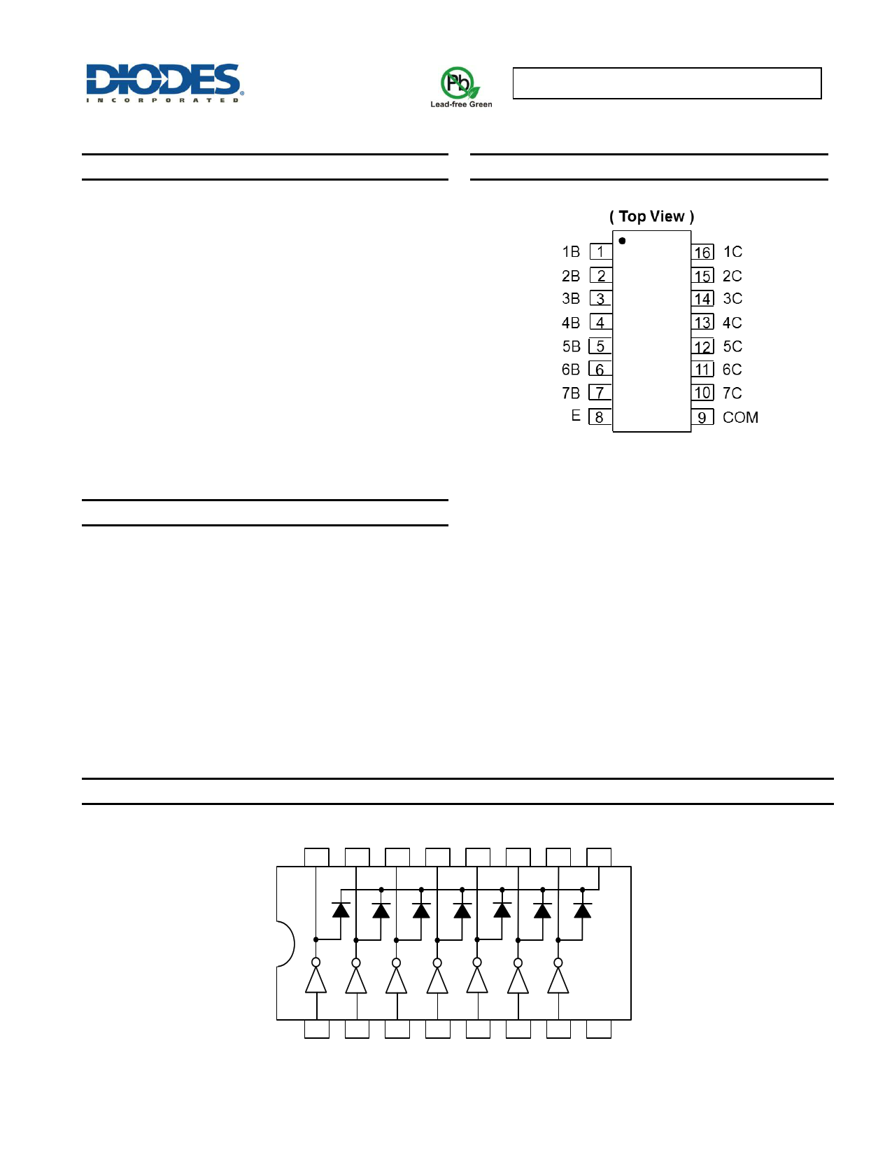
Pin Assignments
Device options are designed to be compatible with common logic
families:
ULN2002A (14-25V PMOS)
ULN2003A (5V TTL, CMOS)
ULN2004A (6-15V CMOS, PMOS)
These devices are capable of driving a wide range of loads including
solenoids, relays, DC motors, LED displays, filament lamps, thermal
print-heads and high-power buffers.
The ULN2002A, 2003A and 2004A are available in both a small
outline 16-pin package (SO-16) and DIP-16 package.
SO-16/DIP-16
Features
500mA Rated Collector Current (single output)
High Voltage Outputs: 50V
Output Clamp Diodes
Inputs Compatible with Popular Logic Types
Relay Driver Applications
“Green” Molding Compound (No Br, Sb)
Totally Lead-Free & Fully RoHS Compliant (Note 1 & 2)
Halogen and Antimony Free. “Green” Device (Note 3)
Notes:
1. No purposely added lead. Fully EU Directive 2002/95/EC (RoHS) & 2011/65/EU (RoHS 2) compliant.
2. See http://www.diodes.com/quality/lead_free.html for more information about Diodes Incorporated’s definitions of Halogen- and Antimony-free, "Green"
and Lead-free.
3. Halogen- and Antimony-free "Green” products are defined as those which contain <900ppm bromine, <900ppm chlorine (<1500ppm total Br + Cl) and
<1000ppm antimony compounds.
Connection Diagram
1C 2C 3C 4C 5C 6C 7C COM
16 15 14 13 12 11 10
9
12345678
1B 2B 3B 4B 5B 6B 7B E
ULN2002A/ ULN2003A/ ULN2004A
Document number: DS35313 Rev. 6 - 2
1 of 13
www.diodes.com
June 2015
© Diodes Incorporated
1 page 
ULN2002A/ ULN2003A/ ULN2004A
Electrical Characteristics (@TA = -40°C to +105°C, unless otherwise specified.)
ULN2003A
Parameter
VI(on) On State Input Voltage
VCE(sat)
Collector Emitter Saturation
Voltage
VF Clamp Forward Voltage
ICEX Collector Cut-off Current
II(off) Off State Input Current
II Input Current
IR Clamp Reverse Current
CI Input Capacitance
Test Figure
6
5
8
1
3
4
7
-
Test Conditions
IC = 200mA
VCE = 2V
IC = 250mA
IC = 300mA
II = 250µA, IC = 100mA
II = 350µA, IC = 200mA
II = 500µA, IC = 350mA
IF = 350mA
VCE = 50V, II = 0
VCE = 50V, IC = 500µA
VI = 3.85V
VR = 50V
VI = 0, f = 1MHz
Min Typ Max Unit
- - 2.7
- - 2.9 V
- -3
- 0.9 1.2
- 1 1.4 V
- 1.2 1.7
- 1.7 2.2 V
- - 100 µA
30 65 - µA
-
0.93 1.35
mA
- - 100 µA
- 15 25 pF
Switching Characteristics (@TA = +25°C, unless otherwise specified.)
ULN2002A, ULN2003A, ULN2004A
Parameter
tPLH Propagation delay time, low to high level output
tPLL Propagation delay time, high to low level output
VOH High level output voltage after switching
Test figure
Min Typ Max Unit
10
- 0.25 1
µs
10
- 0.25 1
µs
10 (VS = 50V, IO = 300mA)
VS-20
-
- mV
Switching Characteristics (@TA = -40 to +105°C, unless otherwise specified.)
ULN2003A
Parameter
tPLH Propagation delay time, low to high level output
tPLL Propagation delay time, high to low level output
VOH High level output voltage after switching
Test figure
10
10
10 (VS = 50V, IO = 300mA)
Min
-
-
VS-50
Typ
1
1
-
Max
10
10
-
Unit
µs
µs
mV
ULN2002A/ ULN2003A/ ULN2004A
Document number: DS35313 Rev. 6 - 2
5 of 13
www.diodes.com
June 2015
© Diodes Incorporated
5 Page 
ULN2002A/ ULN2003A/ ULN2004A
Package Outline Drawings
Please see AP02002 at http://www.diodes.com/datasheets/ap02002.pdf for the latest version.
SO-16
EH
Gauge Plane
L
Detail ‘A’
DA
A2
B
e
A1 C
Detail ‘A’
SO-16
Dim Min
Max
A 1.40 1.75
A1 0.10 0.25
A2 1.30 1.50
B 0.33 0.51
C 0.19 0.25
D 9.80 10.00
E 3.80 4.00
e 1.27 Typ
H 5.80 6.20
L 0.38 1.27
0
8°
All Dimensions in mm
PDIP-16
A
L
b2
be
D
A3
A2
A1
E1
c
PDIP-16
Dim Min Max Nom
A 3.60 4.00 3.80
A1 0.51 -
-
A2 3.20 3.40 3.30
E2c A3 1.47 1.57 1.52
E2a b 0.44 0.53 -
b2 1.52BSC
E2b c 0.25 0.31 -
D 18.90 19.30 19.10
E1 6.15 6.55 6.35
E2a 7.62 BSC
E2b 7.62 9.30 -
E2c 0.00 0.84 -
e 2.54BSC
L 3.00 -
-
All Dimensions in mm
ULN2002A/ ULN2003A/ ULN2004A
Document number: DS35313 Rev. 6 - 2
11 of 13
www.diodes.com
June 2015
© Diodes Incorporated
11 Page | ||
| Páginas | Total 13 Páginas | |
| PDF Descargar | [ Datasheet ULN2003A.PDF ] | |
Hoja de datos destacado
| Número de pieza | Descripción | Fabricantes |
| ULN2003 | 7CH DARLINGTON SINK DRIVER | Unisonic Technologies |
| ULN2003 | SEVEN DARLINGTON ARRAYS | STMicroelectronics |
| ULN2003 | HIGH-VOLTAGE/ HIGH-CURRENT DARLINGTON ARRAYS | Allegro MicroSystems |
| ULN2003 | High Voltage / High Current Darlington Transistor Arrays | Philips |
| Número de pieza | Descripción | Fabricantes |
| SLA6805M | High Voltage 3 phase Motor Driver IC. |
Sanken |
| SDC1742 | 12- and 14-Bit Hybrid Synchro / Resolver-to-Digital Converters. |
Analog Devices |
|
DataSheet.es es una pagina web que funciona como un repositorio de manuales o hoja de datos de muchos de los productos más populares, |
| DataSheet.es | 2020 | Privacy Policy | Contacto | Buscar |