|
|
|
PDF VS-10MQ100-M3 Data sheet ( Hoja de datos )
| Número de pieza | VS-10MQ100-M3 | |
| Descripción | Schottky Rectifier ( Diode ) | |
| Fabricantes | Vishay | |
| Logotipo | ||
Hay una vista previa y un enlace de descarga de VS-10MQ100-M3 (archivo pdf) en la parte inferior de esta página. Total 6 Páginas | ||
|
No Preview Available !
www.vishay.com
VS-10MQ100-M3
Vishay Semiconductors
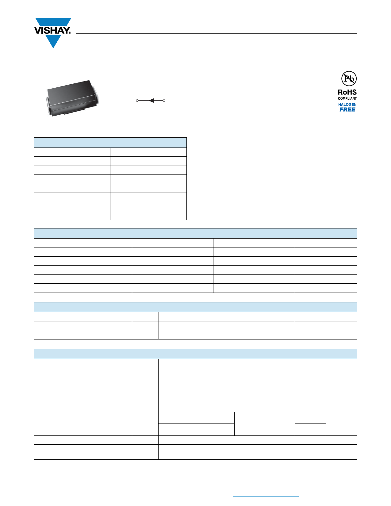
High Performance Schottky Rectifier, 1 A
Cathode
Anode
DO-214AC (SMA)
PRODUCT SUMMARY
Package
IF(AV)
VR
VF at IF
IRM
TJ max.
Diode variation
EAS
DO-214AC (SMA)
1A
100 V
0.63 V
1 mA at 125 °C
150 °C
Single die
1.0 mJ
FEATURES
• Low forward voltage drop
• Guard ring for enhanced ruggedness and long
term reliability
• Small foot print, surface mountable
• High frequency operation
• Meets MSL level 1, per J-STD-020, LF maximum peak
of 260 °C
• Material categorization: for definitions of compliance
please see www.vishay.com/doc?99912
DESCRIPTION
The VS-10MQ100-M3 surface mount Schottky rectifier has
been designed for applications requiring low forward drop
and very small foot prints on PC boards. Typical
applications are in disk drives, switching power supplies,
converters, freewheeling diodes, battery charging, and
reverse battery protection.
MAJOR RATINGS AND CHARACTERISTICS
SYMBOL
CHARACTERISTICS
IF(AV)
VRRM
Rectangular waveform
IFSM
tp = 5 μs sine
VF 1.5 Apk, TJ = 125 °C
TJ Range
VALUES
1
100
120
0.68
-55 to +150
UNITS
A
V
A
V
°C
VOLTAGE RATINGS
PARAMETER
SYMBOL
Maximum DC reverse voltage
VR
Maximum working peak reverse voltage VRWM
VS-10MQ100-M3
100
UNITS
V
ABSOLUTE MAXIMUM RATINGS
PARAMETER
SYMBOL
Maximum average forward current
See fig. 4
IF(AV)
Maximum peak one cycle
non-repetitive surge current, TJ = 25 °C
See fig. 6
Non-repetitive avalanche energy
Repetitive avalanche current
IFSM
EAS
IAR
TEST CONDITIONS
50 % duty cycle at TL = 126 °C, rectangular waveform
On PC board 9 mm2 island
(0.013 mm thick copper pad area)
50 % duty cycle at TL = 135 °C, rectangular waveform
On PC board 9 mm2 island
(0.013 mm thick copper pad area)
5 μs sine or 3 μs rect. pulse
10 ms sine or 6 ms rect. pulse
Following any rated
load condition and with
rated VRRM applied
TJ = 25 °C, IAS = 0.5 A, L = 8 mH
Current decaying linearly to zero in 1 μs
Frequency limited by TJ maximum VA = 1.5 x VR typical
VALUES
1.5
1
120
30
1.0
0.5
UNITS
A
mJ
A
Revision: 20-Jan-15
1 Document Number: 93365
For technical questions within your region: [email protected], [email protected], [email protected]
THIS DOCUMENT IS SUBJECT TO CHANGE WITHOUT NOTICE. THE PRODUCTS DESCRIBED HEREIN AND THIS DOCUMENT
ARE SUBJECT TO SPECIFIC DISCLAIMERS, SET FORTH AT www.vishay.com/doc?91000
1 page 
SMA
Outline Dimensions
Vishay Semiconductors
DIMENSIONS in inches (millimeters)
DO-214AC (SMA)
Cathode band
0.065 (1.65)
0.049 (1.25)
0.090 (2.29)
0.078 (1.98)
0.060 (1.52)
0.030 (0.76)
0.177 (4.50)
0.157 (3.99)
0.008 (0.203)
0 (0)
0.208 (5.28)
0.194 (4.93)
0.110 (2.79)
0.100 (2.54)
0.012 (0.305)
0.006 (0.152)
Mounting Pad Layout
0.074 (1.88)
MAX.
0.066 (1.68)
MIN.
0.060 (1.52)
MIN.
0.208 (5.28)
REF.
Document Number: 95400 For technical questions within your region, please contact one of the following:
Revision: 09-Jul-10
www.vishay.com
1
5 Page | ||
| Páginas | Total 6 Páginas | |
| PDF Descargar | [ Datasheet VS-10MQ100-M3.PDF ] | |
Hoja de datos destacado
| Número de pieza | Descripción | Fabricantes |
| VS-10MQ100-M3 | Schottky Rectifier ( Diode ) | Vishay |
| Número de pieza | Descripción | Fabricantes |
| SLA6805M | High Voltage 3 phase Motor Driver IC. |
Sanken |
| SDC1742 | 12- and 14-Bit Hybrid Synchro / Resolver-to-Digital Converters. |
Analog Devices |
|
DataSheet.es es una pagina web que funciona como un repositorio de manuales o hoja de datos de muchos de los productos más populares, |
| DataSheet.es | 2020 | Privacy Policy | Contacto | Buscar |