|
|
|
PDF PS9121 Data sheet ( Hoja de datos )
| Número de pieza | PS9121 | |
| Descripción | 5-PIN SOP (SO-5) 3.3V PHOTOCOUPLER | |
| Fabricantes | Renesas | |
| Logotipo | ||
Hay una vista previa y un enlace de descarga de PS9121 (archivo pdf) en la parte inferior de esta página. Total 15 Páginas | ||
|
No Preview Available !
DATA SHEET
PHOTOCOUPLER
PS9121
HIGH CMR, 15 Mbps OPEN COLLECTOR OUTPUT TYPE
5-PIN SOP (SO-5) 3.3 V PHOTOCOUPLER −NEPOC Series−
DESCRIPTION
The PS9121 is an optically coupled high-speed, active low type isolator containing a GaAlAs LED on the input side
and a photodiode and a signal processing circuit on the output side on one chip.
The PS9121 is designed specifically for high common mode transient immunity (CMR) and low pulse width
distortion. The PS9121 is suitable for high density application.
FEATURES
• Low power consumption (VCC = 3.3 V)
• Pulse width distortion (⏐tPHL − tPLH⏐ = 35 ns MAX.)
• High common mode transient immunity (CMH, CML = ±15 kV/μs MIN.)
• Small package (SO-5)
• High-speed (15 Mbps)
• High isolation voltage (BV = 3 750 Vr.m.s.)
• Open collector output
• Ordering number of taping product: PS9121-F3, F4: 2 500 pcs/reel
• Pb-Free product
• Safety standards
• UL approved: File No. E72422
• DIN EN60747-5-2 (VDE0884 Part2) approved No.40008902 (option)
APPLICATIONS
• Measurement equipment
• PDP
• FA Network
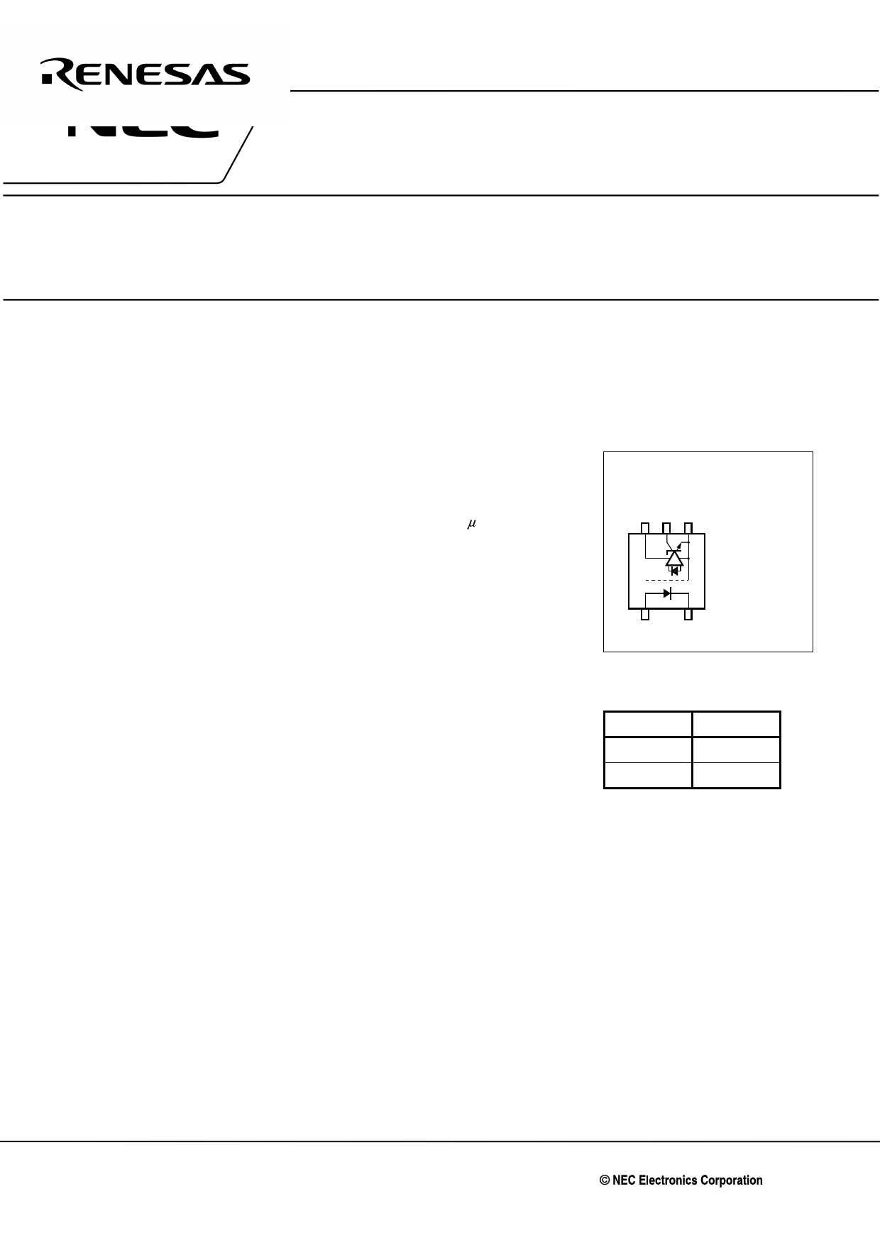
PIN CONNECTION
(Top View)
543
12
1. Anode
2. Cathode
3. GND
4. VO
5. VCC
TRUTH TABLE
LED Output
ON L
OFF H
The information in this document is subject to change without notice. Before using this document, please
confirm that this is the latest version.
Not all products and/or types are available in every country. Please check with an NEC Electronics
sales representative for availability and additional information.
Document No. PN10502EJ05V0DS (5th edition)
Date Published August 2008 NS
Printed in Japan
The mark <R> shows major revised points.
The revised points can be easily searched by copying an "<R>" in the PDF file and specifying it in the "Find what:" field.
2004, 2008
1 page 
PS9121
ELECTRICAL CHARACTERISTICS (TA = −40 to +85°C, unless otherwise specified)
Parameter
Symbol
Conditions
Diode Forward Voltage
VF IF = 10 mA, TA = 25°C
Reverse Current
IR VR = 3 V, TA = 25°C
Terminal Capacitance
Ct V = 0 V, f = 1 MHz, TA = 25°C
Detector High Level Output Current
IOH VCC = VO = 3.3 V, VF = 0.8 V
Low Level Output Voltage*3
VCC = VO = 5.5 V, VF = 0.8 V
VOL VCC = 3.3 V, IF = 5 mA, IOL = 13 mA
VCC = 5.5 V, IF = 5 mA, IOL = 13 mA
High Level Supply Current
ICCH VCC = 3.3 V, IF = 0 mA, VO = Open
VCC = 5.5 V, IF = 0 mA, VO = Open
Low Level Supply Current
ICCL VCC = 3.3 V, IF = 10 mA, VO = Open
VCC = 5.5 V, IF = 10 mA, VO = Open
Coupled Threshold Input Current
IFHL VCC = 3.3 V, VO = 0.8 V, RL = 350 Ω
(H → L)
VCC = 5 V, VO = 0.8 V, RL = 350 Ω
Isolation Resistance
RI-O VI-O = 1 kVDC, RH = 40 to 60%,
TA = 25°C
Isolation Capacitance
CI-O V = 0 V, f = 1 MHz, TA = 25°C
Propagation Delay Time
(H → L)*4
tPHL TA = 25°C
VCC = 3.3 V, RL = 350 Ω, IF = 7.5 mA
VCC = 5 V, RL = 350 Ω, IF = 7.5 mA
Propagation Delay Time
(L → H)*4
tPLH TA = 25°C
VCC = 3.3 V, RL = 350 Ω, IF = 7.5 mA
VCC = 5 V, RL = 350 Ω, IF = 7.5 mA
Rise Time
tr VCC = 3.3 V, RL = 350 Ω, IF = 7.5 mA
VCC = 5 V, RL = 350 Ω, IF = 7.5 mA
Fall Time
tf VCC = 3.3 V, RL = 350 Ω, IF = 7.5 mA
VCC = 5 V, RL = 350 Ω, IF = 7.5 mA
Pulse Width Distortion
(PWD)*4
⏐tPHL-tPLH⏐ VCC = 3.3 V, RL = 350 Ω, IF = 7.5 mA
VCC = 5 V, RL = 350 Ω, IF = 7.5 mA
Propagation Delay Skew
tPSK VCC = 3.3 V, RL = 350 Ω, IF = 7.5 mA
Common Mode
Transient Immunity at High
Level Output*5
CMH
VCC = 3.3 V, RL = 350 Ω, TA = 25°C,
IF = 0 mA, VO > 2 V, VCM = 1 kV
VCC = 5 V, RL = 350 Ω, TA = 25°C,
IF = 0 mA, VO > 2 V, VCM = 1 kV
Common Mode
Transient Immunity at Low
Level Output*5
CML
VCC = 3.3 V, RL = 350 Ω, TA = 25°C,
IF = 7.5 mA, VO < 0.8 V, VCM = 1 kV
VCC = 5 V, RL = 350 Ω, TA = 25°C,
IF = 7.5 mA, VO < 0.8 V, VCM = 1 kV
MIN.
1.4
1011
TYP.*1
1.65
30
1
1*2
0.2
0.2*2
4
5*2
7
9*2
2.5
2.5*2
MAX.
1.8
10
80
0.6
7
10
5
Unit
V
μA
pF
μA
V
mA
Ω
0.6 pF
40 75 ns
100
37*2
45 75
100
40*2
20
20*2
5
5*2
5 35
3*2
40
15 20
kV/μs
20*2
15 20
20*2
Data Sheet PN10502EJ05V0DS
5
5 Page 
PS9121
NOTES ON HANDLING
1. Recommended soldering conditions
(1) Infrared reflow soldering
• Peak reflow temperature
• Time of peak reflow temperature
• Time of temperature higher than 220°C
• Time to preheat temperature from 120 to 180°C
• Number of reflows
• Flux
260°C or below (package surface temperature)
10 seconds or less
60 seconds or less
120±30 s
Three
Rosin flux containing small amount of chlorine (The flux with a
maximum chlorine content of 0.2 Wt% is recommended.)
Recommended Temperature Profile of Infrared Reflow
180˚C
120˚C
120±30 s
(preheating)
(heating)
to 10 s
to 60 s
260˚C MAX.
220˚C
Time (s)
(2) Wave soldering
• Temperature
• Time
• Preheating conditions
• Number of times
• Flux
260°C or below (molten solder temperature)
10 seconds or less
120°C or below (package surface temperature)
One (Allowed to be dipped in solder including plastic mold portion.)
Rosin flux containing small amount of chlorine (The flux with a maximum chlorine
content of 0.2 Wt% is recommended.)
(3) Soldering by Soldering Iron
• Peak Temperature (lead part temperature)
• Time (each pins)
• Flux
350°C or below
3 seconds or less
Rosin flux containing small amount of chlorine (The flux with a
maximum chlorine content of 0.2 Wt% is recommended.)
(a) Soldering of leads should be made at the point 1.5 to 2.0 mm from the root of the lead
(b) Please be sure that the temperature of the package would not be heated over 100°C
Data Sheet PN10502EJ05V0DS
11
11 Page | ||
| Páginas | Total 15 Páginas | |
| PDF Descargar | [ Datasheet PS9121.PDF ] | |
Hoja de datos destacado
| Número de pieza | Descripción | Fabricantes |
| PS9121 | 5-PIN SOP (SO-5) 3.3V PHOTOCOUPLER | Renesas |
| PS9122 | 1 Mbps OPEN COLLECTOR OUTPUT TYPE 5-PIN SOP (SO-5) HIGH-SPEED PHOTOCOUPLER | California Eastern Labs |
| PS9123 | HIGH CMR 15Mbps TOTEM POLE OUTPUT TYPE 5-PIN SOP (SO-5) PHOTOCOUPLER | California Eastern Labs |
| Número de pieza | Descripción | Fabricantes |
| SLA6805M | High Voltage 3 phase Motor Driver IC. |
Sanken |
| SDC1742 | 12- and 14-Bit Hybrid Synchro / Resolver-to-Digital Converters. |
Analog Devices |
|
DataSheet.es es una pagina web que funciona como un repositorio de manuales o hoja de datos de muchos de los productos más populares, |
| DataSheet.es | 2020 | Privacy Policy | Contacto | Buscar |