|
|
|
PDF IMS-5 Data sheet ( Hoja de datos )
| Número de pieza | IMS-5 | |
| Descripción | Inductors | |
| Fabricantes | Vishay | |
| Logotipo | ||
Hay una vista previa y un enlace de descarga de IMS-5 (archivo pdf) en la parte inferior de esta página. Total 2 Páginas | ||
|
No Preview Available !
IMS-5
Vishay Dale
Inductors
Military, MIL-PRF-15305 Qualified, Type LT
and Commercial, Molded, Shielded
FEATURES
• Wide inductance range in small package.
• Flame retardant coating.
• Electromagnetic shield-finest shield available.
• Epoxy molded construction provides superior moisture
protection.
• Precision performance, excellent reliability, sturdy construction.
INDUCTANCE RANGE AND MILITARY STANDARD
INDUCTANCE
RANGE CLASSIFICATION MATERIAL
MILITARY
FROM TO GRADE CLASS CORE SHIELD STANDARD
.10µH .82µH
1.0µH 12.0µH
15.0µH 100,000µH
1
1
1
A Phenolic Powd. Iron MS75087
A Powd. Iron Powd. Iron MS75088
A Ferrite Ferrite MS75089*
*Not QPL'd.
ENVIRONMENTAL PERFORMANCE
TEST
CONDITIONS SPECIFICATIONS
Barometric Pressure Test Condition C MIL-STD-202, Method 105
Thermal Shock
Test Condition A-1 MIL-STD-202, Method 107
ELECTRICAL SPECIFICATIONS
Inductance Tolerance: ± 10% standard.
± 5% available.
Insulation Resistance: 1000 Megohm minimum per
MIL-STD-202, Method 302, Test Condition B.
Dielectric Withstanding Voltage: 1000 VAC per
MIL-STD-202, Method 301 (sea level).
Percent Coupling: 3% maximum per MIL-PRF-15305.
Operating Temperature Range: - 55°C to + 105°C.
MECHANICAL SPECIFICATIONS
Terminal Strength: 5 pounds pull per MIL-STD-202,
Method 211, Test Condition A.
Weight: IMS-5 = 0.85 grams maximum.
MATERIAL SPECIFICATIONS
Encapsulant: Epoxy.
Standard Terminal: #22 AWG tinned copper.
Flammability
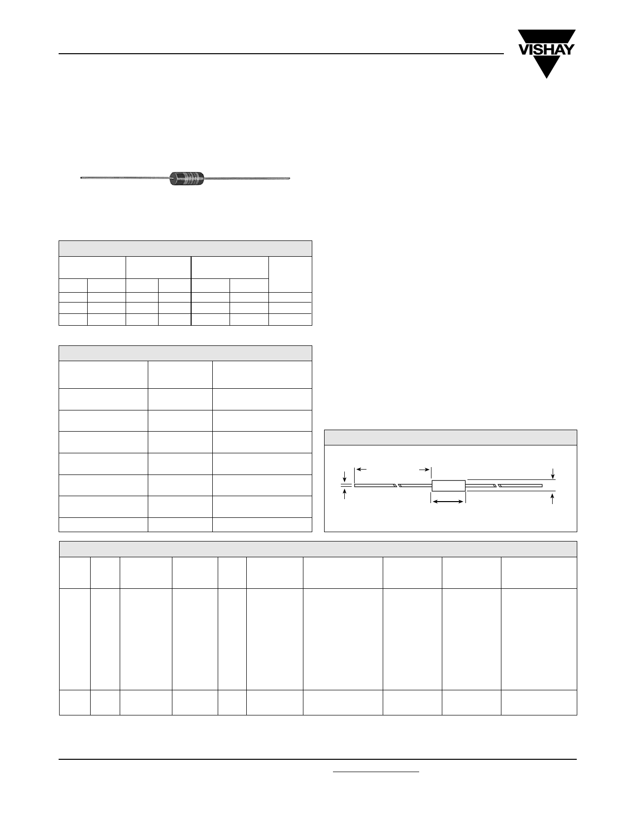
— MIL-STD-202, Method 111 DIMENSIONS in inches [millimeters]
Overload
— MIL-PRF-15305
Low Temperature
Storage
—
Resistance to
Soldering Heat
Test Condition A
Resistance to Solvents
—
MIL-PRF-15305
MIL-STD-202, Method 210
MIL-STD-202, Method 215
1.44 ± 0.188
[36.57 ± 4.78]
0.025 ± 0.002
[0.635 ± 0.051]
0.410 ± 0.020
[10.41 ± 0.508]
0.162 ± 0.010
[4.11 ± .254]
STANDARD ELECTRICAL SPECIFICATIONS
TEST FREQ. SELF-RESONANT * DCR @ 2°5C RATED DC ** INCREMENTAL***
IND.
MILITARY MILITARY Q
L&Q
FREQ. MIN.
MAX.
CURRENT
CURRENT
(µH) TOL. STANDARD TYPE MIN.
(MHz)
(MHz)
(Ohms)
(mA)
(mA)
MS75087
0.10 ± 10%
0.12 ± 10%
0.15 ± 10%
0.18 ± 10%
0.22 ± 10%
0.27 ± 10%
0.33 ± 10%
0.39 ± 10%
0.47 ± 10%
0.56 ± 10%
0.68 ± 10%
0.82 ± 10%
-1
-2
-3
-4
-5
-6
-7
-8
-9
-10
-11
-12
MS75088
1.0 ± 10%
1.2 ± 10%
-1
-2
LT10K
191
192
193
194
195
196
197
198
199
200
201
202
LT10K
203
204
50
51
51
50
49
47
46
44
44
43
42
40
44
44
25.0
25.0
25.0
25.0
25.0
25.0
25.0
25.0
25.0
25.0
25.0
25.0
25.0
7.9
250.0
250.0
250.0
250.0
250.0
250.0
250.0
250.0
235.0
210.0
190.0
180.0
140.0
130.0
0.025
0.034
0.037
0.047
0.067
0.11
0.13
0.18
0.25
0.33
0.45
0.59
0.07
0.10
1790
1530
1470
1300
1100
855
780
670
565
490
420
370
1070
895
—
—
—
—
—
—
—
—
—
—
—
—
—
—
*Measured with full length lead. **Rated DC Current: Based on maximum temperature rise not to exceed 15°C at + 90°C ambient.
***Incremental Current: The minimum typical current at which the inductance will be decreased by 5% from its initial zero DC value.
NOTE: Listing of Military Standard does not imply qualification. Contact factory for latest government QPL information.
www.vishay.com
24
For technical questions, contact [email protected]
Document Number 34048
Revision 18-Oct-04
1 page | ||
| Páginas | Total 2 Páginas | |
| PDF Descargar | [ Datasheet IMS-5.PDF ] | |
Hoja de datos destacado
| Número de pieza | Descripción | Fabricantes |
| IMS-2 | Inductors Commercial | Vishay Siliconix |
| IMS-2SWWD-3 | Inductors | Vishay Siliconix |
| IMS-2SWWD-30 | Inductors | Vishay Siliconix |
| IMS-2WWD-40 | Inductors | Vishay Siliconix |
| Número de pieza | Descripción | Fabricantes |
| SLA6805M | High Voltage 3 phase Motor Driver IC. |
Sanken |
| SDC1742 | 12- and 14-Bit Hybrid Synchro / Resolver-to-Digital Converters. |
Analog Devices |
|
DataSheet.es es una pagina web que funciona como un repositorio de manuales o hoja de datos de muchos de los productos más populares, |
| DataSheet.es | 2020 | Privacy Policy | Contacto | Buscar |