|
|
|
PDF IL1815 Data sheet ( Hoja de datos )
| Número de pieza | IL1815 | |
| Descripción | Adaptive Variable Reluctance Sensor Amplifier | |
| Fabricantes | Integral | |
| Logotipo | ||
Hay una vista previa y un enlace de descarga de IL1815 (archivo pdf) en la parte inferior de esta página. Total 5 Páginas | ||
|
No Preview Available !
TECHNICAL DATA
IL1815 Adaptive Variable Reluctance Sensor Amplifier
Features
• Adaptive hysteresis
• Single supploperation
• Ground referenced input
• True zero crossing timing reference
• Operates from 2V to 12V supply voltage
• Handles inputs from 100 mV to over
120V with external resistor
• CMOS compatible logic
Applications
• Position sensing with notched wheels
• Zero crossing switch
• Motor speed control
• Tachometer
• Engine testing
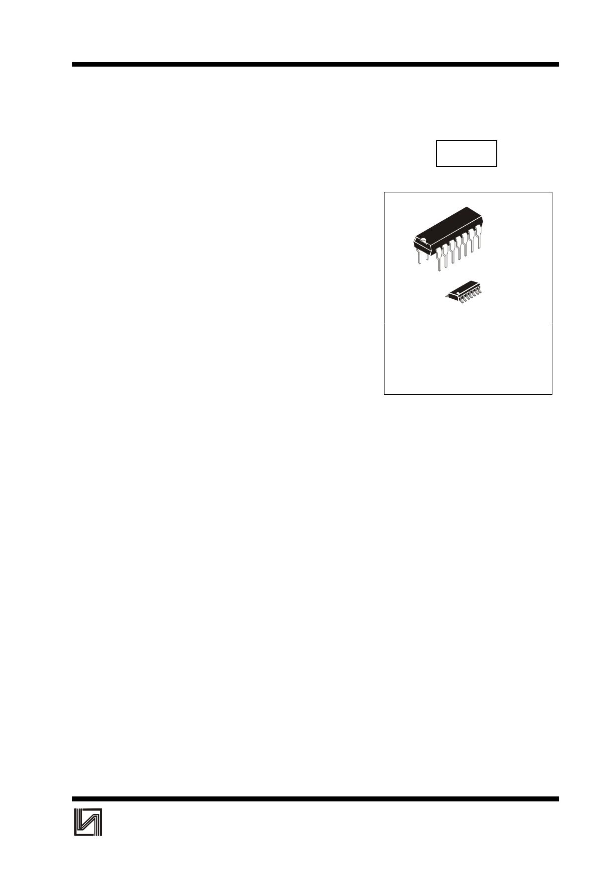
IL1815
N SUFFIX
PLASTIC DIP
14
1
14
1
D SUFFIX
PLASTIC SO
ORDERING INFORMATION
IL1815N Plastic DIP
IL1815D SOIC
TA = -55° to 125° C for all packages
General Description
The IL1815 is an adaptive sense amplifier and default gating circuit for motor control
applications. The sense amplifier provides a one-shot pulse output whose leading edge coincides
with the negative-going zero crossing of a ground referenced input signal such as from a variable
reluctance magnetic pick-up coil. In normal operation, this timing reference signal is processed
(delayed) externally and returned to the IL1815. A logic input is then able to select either the
timing reference or the processed signal for transmission to the output driver stage. The adaptive
sense amplifier operates with a positive-going threshold which is derived by peak detecting the
incoming signal and dividing this down. Thus the input hysteresis varies with input signal
amplitude. This enables the circuit to sense in situations where the high speed noise is greater
than the low speed signal amplitude. Minimum input signal is 100 mVp-p.
INTEGRAL
1
1 page 
IL1815
MODE 2, Pin 5 connected to Va. The input arming threshold is fixed at 200 mV minimum
when pin 5 is connected to the positive supply. The chip has no output for signals of less than
200 mV peak, and triggers on the next negativegoing zero crossing when the threshold is
exceeded.
MODE 3, Pin 5 grounded. With pin 5 grounded, the input arming threshold is set to 0V (±25
mV maximum). Positivegoing zero crossings arm the chip, and the next negative zero crossing
triggers it.
The one shot timing is set by a resistor and capacitor connected to pin 14. The output pulse width
is
pulse width = 0.673 RC
(1)
In some systems it is necessary to externally generate pulses, such as during stall conditions
when the variable reluctance sensor has no output. External pulse inputs at pin 9 are gated
through to pin 10 when Input Select (pin 11) is pulled high. Pin 12 is a direct output for the one
shot and is unaffected by the status of pin 11. Input/output pins 9, 11, 10 and 12 are all CMOS
logic compatible. In addition, pins 9, 11 and 12 are TTL compatible. Pin 10 is not guaranteed to
drive a TTL load. Pins 1, 4, 6 and 13 have no internal connections and can be grounded.
INTEGRAL
5
5 Page | ||
| Páginas | Total 5 Páginas | |
| PDF Descargar | [ Datasheet IL1815.PDF ] | |
Hoja de datos destacado
| Número de pieza | Descripción | Fabricantes |
| IL1815 | Adaptive Variable Reluctance Sensor Amplifier | Integral |
| IL1815 | AMPLIFIER IC FOR SENSORS WITH DIFFERENT CONDUCTANCE | Integral |
| Número de pieza | Descripción | Fabricantes |
| SLA6805M | High Voltage 3 phase Motor Driver IC. |
Sanken |
| SDC1742 | 12- and 14-Bit Hybrid Synchro / Resolver-to-Digital Converters. |
Analog Devices |
|
DataSheet.es es una pagina web que funciona como un repositorio de manuales o hoja de datos de muchos de los productos más populares, |
| DataSheet.es | 2020 | Privacy Policy | Contacto | Buscar |