|
|
|
PDF TPF632 Data sheet ( Hoja de datos )
| Número de pieza | TPF632 | |
| Descripción | Audio Line Driver | |
| Fabricantes | 3Peak | |
| Logotipo | ||
Hay una vista previa y un enlace de descarga de TPF632 (archivo pdf) en la parte inferior de esta página. Total 9 Páginas | ||
|
No Preview Available !
3PEAK
Features
TPF632
2-VRMS Audio Line Driver with Integrated Charge Pump
Description
2-VRMS Output into 2.5kΩ Load with 3.3V Supply
Integrated Charge Pump Generates Negative
Supply Rail
0-V DC Voltage at Output
Low Noise: VN = 4.3μVRMS at 20Hz to 20kHz
Low THD+N: 0.001%
Drives 600Ω Load
Stable with 220pF Capacitive Load
Pop-Free Under-Voltage Protection
Pop-Free Enable Control
–40°C to 85°C Operation Range
Robust 8kV (Output) HBM ESD Rating
Robust 2kV CDM ESD Rating
Green, TSSOP-14 Package
Applications
Set-Top Box
Blu-ray and HD DVD Players
PDP TV and LCD TV
Home Theater in a Box
The 3PEAK INCORPORATED TPF632 are 2-VRMS
pop-free stereo line drivers with the integrated
charge pump generating the negative supply rail
which allows the removal of the output DC-blocking
capacitors. The devices are capable of driving
2-VRMS into a 2.5-kΩ load with single 3.3V supply
voltage. The device has differential inputs, and can
use external resistors for flexible gain setting.
The TPF632 has built-in enable/shutdown control
for pop-free on/off control. The device has an
external under-voltage detector that mutes the
output when monitored voltage drop below set value.
Using the TPF632 in audio products can reduce
component count considerably compared to
traditional methods of generating a 2-VRMS output.
The device needs only a single 3.3V supply to
generate 5.6-VPP output while a traditional op-amp
requires a split-rail power supply to achieve same.
The device is ideal for single-supply electronics
where size and cost are critical design parameters.
3PEAK and the 3PEAK logo are registered trademarks of
3PEAK INCORPORATED. All other trademarks are the property
of their respective owners.
Audio Line Drivers
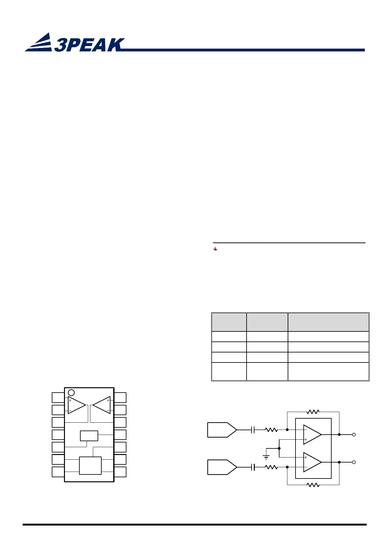
Pin Configuration (Top View)
TPF632
14-Pin TSSOP
+INR 1
-INR 2
OUTR 3
GND 4
EN 5
PVSS 6
CN 7
UVP
Charge
Pump
14 +INL
13 -INL
12 OUTL
11 UVP
10 PGND
9 PVDD
8 CP
Part
Number
TPF632
TPF603
TPF605
TPF607
Package
Remarks
TSSOP-14
TSSOP-14
MSOP-10-EP
MSOP-10
3.3V, Differential inputs
5V/3.3V, Differential inputs
5V/3.3V, Single-ended inputs
5V/3.3V, Single-ended inputs,
no UVP control
DAC
DAC
TPF632
LEFT
RIGHT
www.3peakic.com
Figure 1. Typical Application Circuit of TPF632
REV0.0
1
1 page 
Applications Information
Typical Application Circuit
TPF632
2-VRMS Audio Line Driver with Integrated Charge Pump
-VINR
VOUTR
CIN RIN RFB
GND UVP
EN
PVSS
1µF Charge Pump
CN
RFB
RIN
CIN
UVP
PGND
PVDD
CP
1µF
-VINL
VOUTL
1µF
Figure 2 Typical Application Circuit of TPF632
Typical application circuits are shown as above. TPF632 operates from a single supply voltage PVDD. It integrated
charge pump generates a negative supply –PVDD at the PVSS pin. The Line driving amplifiers work with dual supplies:
PVDD and –PVDD. Therefore, the DC level of the audio output can be designed to be 0V. A DC-blocking capacitor
typically seen in a single-supplied driver is not necessary.
The supply range of the TPF632 is 3.0V to 3.63V. For a 2VRMS output, the recommended supply voltage is 3.3V.RIN of
2.5k and RFB of 5k set the inverting gain of 2. Because of the exceptional noise performance of TPF632, the
dominant noise source is actually from RIN. To get better noise performance, lower input resistance and feedback
resistance may be used.
Integrated Charge Pump
The integrated charge pump in TPF632 generates negative power supply from a single supply PVDD. A flying
capacitor for the charge pump shall be applied between CP and CN. At the same time a decoupling capacitor shall be
applied between PVSS and ground. Typical value for the flying capacitor is 1uF. Typical value of the decoupling
capacitor shall be same as or larger than that of the flying capacitor. Low-ESR capacitors are recommended for the
flying capacitor and the decoupling capacitor.
Audio Signal Amplification Gain Setting
The main application of the TPF632 is to amplify/buffer audio signals and drive audio lines with very low distortion.
Typical application circuits with inverting gain are shown in Figure 3.
Non-inverting amplification of audio signals is also possible with same low distortion.
www.3peakic.com
REV0.0
5
5 Page | ||
| Páginas | Total 9 Páginas | |
| PDF Descargar | [ Datasheet TPF632.PDF ] | |
Hoja de datos destacado
| Número de pieza | Descripción | Fabricantes |
| TPF632 | Audio Line Driver | 3Peak |
| Número de pieza | Descripción | Fabricantes |
| SLA6805M | High Voltage 3 phase Motor Driver IC. |
Sanken |
| SDC1742 | 12- and 14-Bit Hybrid Synchro / Resolver-to-Digital Converters. |
Analog Devices |
|
DataSheet.es es una pagina web que funciona como un repositorio de manuales o hoja de datos de muchos de los productos más populares, |
| DataSheet.es | 2020 | Privacy Policy | Contacto | Buscar |