|
|
|
PDF JW5015 Data sheet ( Hoja de datos )
| Número de pieza | JW5015 | |
| Descripción | 40V Synchronous Rectified Step-Down Converter | |
| Fabricantes | JoulWatt | |
| Logotipo | ||
Hay una vista previa y un enlace de descarga de JW5015 (archivo pdf) en la parte inferior de esta página. Total 6 Páginas | ||
|
No Preview Available !
FEATURES
z 3.6V to 40V operating input range
2A output current
z Up to 94% efficiency
z High efficiency (>78%) at light load
z Internal Soft-Start
z Adjustable switching frequency
z Input under voltage lockout
z Available in thermally enhanced ESOP8
package
z Start-up current run-away protection
z Short circuit protection
z Thermal protection
2A, 40V Synchronous Rectified
Step-Down Converter
under voltage lockout.
The JW5015 is available in 8-pin ESOP package,
which provides a compact solution with minimal
external components. The package has an
exposed pad for low thermal resistance.
APPLICATIONS
z Distributed Power Systems
z Networking Systems
z FPGA, DSP, ASIC Power Supplies
z Green Electronics/ Appliances
z Notebook Computers
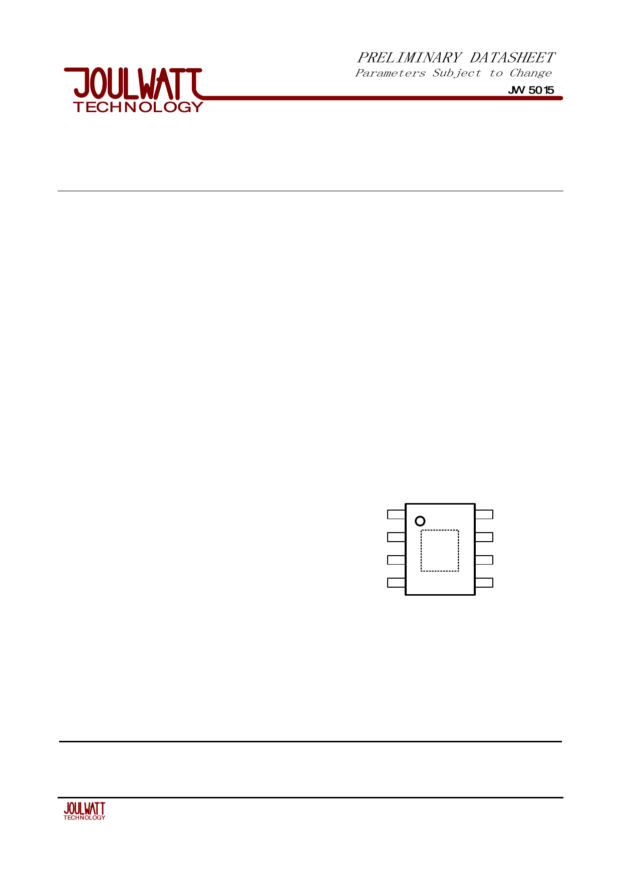
PIN CONFIGURATION
DESCRIPTION
The JW5015 is a current mode monolithic buck
switching regulator. Operating with an input range
of 3.6-40V, the JW5015 delivers 2A of continuous
output current with two integrated N-Channel
MOSFETs. The internal synchronous power
switches provide high efficiency without the use of
an external Schottky diode. At light loads,
regulators operate in low frequency to maintain
high efficiency and low output ripple. Current
mode control provides tight load transient
response and cycle-by-cycle current limit.
The JW5015 guarantees robustness with
short-circuit protection, thermal protection,
start-up current run-away protection, and input
TOP VIEW
SW 1
8 VIN
BST 2
VD 3
9 GND
7 EN
6 RT
FB 4
5 COMP
ESOP 8
EXPOSED PAD(PIN 9) IS GND, MUST BE
SOLDERED TO PCB
JW5015
REV: 0.1 1 / 6
1 page 
JW5015
FUNCTIONAL DESCRIPTION
The JW5015 is a synchronous, current-mode,
step-down regulator. It regulates input voltages
from 3.6V to 40V down to an output voltage as
low as 0.8V, and is capable of supplying up to 2A
of load current.
Current-Mode Control
The JW5015 utilizes current-mode control to
regulate the output voltage. The output voltage is
measured at the FB pin through a resistive
voltage divider and the error is amplified by the
internal transconductance error amplifier. COMP
pin is output of the internal error amplifier and is
compared to the switch current measured
internally to control the output current limit.
PFM Mode
The JW5015 operates in PFM mode at light load.
In PFM mode, switch frequency is continuously
controlled in proportion to the load current, i.e.
switch frequency is decreased when load current
drops to boost power efficiency at light load by
reducing switch-loss, while switch frequency is
increased when load current rises, minimizing
both load current and output voltage ripples.
Shut-Down Mode
The JW5015 operates in shut-down mode when
voltage at EN pin is driven below 0.3V. In
shut-down mode, the entire regulator is off and
the supply current consumed by the JW5015
drops below 0.1uA.
Power Switch
N-Channel MOSFET switches are integrated on
the JW5015 to down convert the input voltage to
the regulated output voltage. Since the top
MOSFET needs a gate voltage great than the
input voltage, a boost capacitor connected
between BST and SW pins is required to drive the
gate of the top switch. The boost capacitor is
charged by the internal 3.3V rail when SW is low.
Vin Under-Voltage Protection
A resistive divider can be connected between Vin
and ground, with the central tap connected to EN,
so that when Vin drops to the pre-set value, EN
drops below 1.2V to trigger input under voltage
lockout protection.
Vout Over-Voltage Protection
When output voltage rises above its regulated
value, both the top and bottom power switches
are turned off. Switching of the internal clock is
also disabled. Only when output voltage falls to its
regulated value can the internal clock, top power
switch, and bottom power switch become active
again.
Output Current Run-Away Protection
At start-up, due to the high voltage at input and
low voltage at output, current inertia of the output
inductance can be easily built up, resulting in a
large start-up output current. A valley current limit
is designed in the JW5015 so that only when
output current drops below the valley current limit
can the bottom power switch be turned off. By
such control mechanism, the output current at
start-up is well controlled.
Output Short Protection
When output is shorted to ground, output current
rapidly reaches its peak current limit and the top
power switch is turned off. Right after the top
power switch is turned off, the bottom power
switch is turned on and stay on until the output
JW5015
REV: 0.1 5 / 6
5 Page | ||
| Páginas | Total 6 Páginas | |
| PDF Descargar | [ Datasheet JW5015.PDF ] | |
Hoja de datos destacado
| Número de pieza | Descripción | Fabricantes |
| JW5015 | 40V Synchronous Rectified Step-Down Converter | JoulWatt |
| JW5015B | 40V Synchronous Step-Down Converter | JoulWatt |
| Número de pieza | Descripción | Fabricantes |
| SLA6805M | High Voltage 3 phase Motor Driver IC. |
Sanken |
| SDC1742 | 12- and 14-Bit Hybrid Synchro / Resolver-to-Digital Converters. |
Analog Devices |
|
DataSheet.es es una pagina web que funciona como un repositorio de manuales o hoja de datos de muchos de los productos más populares, |
| DataSheet.es | 2020 | Privacy Policy | Contacto | Buscar |