|
|
|
PDF 7401-4658 Data sheet ( Hoja de datos )
| Número de pieza | 7401-4658 | |
| Descripción | CONTACTOR | |
| Fabricantes | Esterline | |
| Logotipo | ||
Hay una vista previa y un enlace de descarga de 7401-4658 (archivo pdf) en la parte inferior de esta página. Total 12 Páginas | ||
|
No Preview Available !
ENGINEERING DATA SHEET
7401-4658
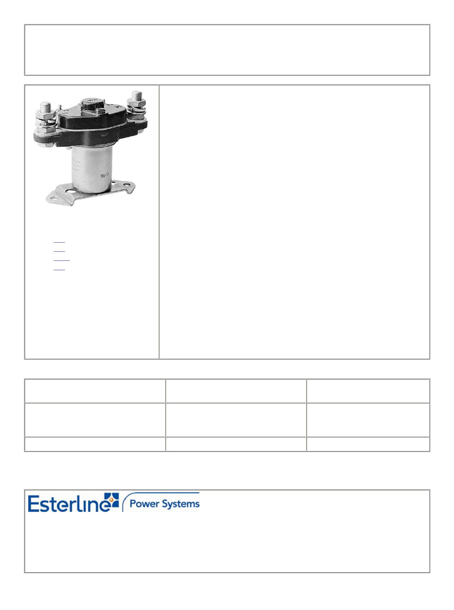
CONTACTOR
1PST-DM, 400 AMP
Non latching solenoid design power contactor
Qualified to
MIL-PRF-6106
MS24185-D1
AN-3380-1
PRINCIPLE TECHNICAL CHARACTERISTICS
Contacts rated at
400 Amps / 28 Vdc
Weight
1180g max.
Dimensions of case
139.7mm x 62mm x 44.3mm max.
Special units available upon request.
APPLICATION NOTES:
101
102
103G
007
CONTACT ELECTRICAL CHARACTERISTICS
Minimum operating cycles
Contact rating per
pole and load type
50,000 cycles
50,000 cycles
50,000 cycles
resistive
inductive (L/R=5ms)
motor
50,000 cycles
minimum current (Amps)
Load Current in Amps
@28Vdc
400
100
400
40
Featuring LEACH© power and control solutions
www.esterline.com
AMERICAS
6900 Orangethorpe Ave.
P.O. Box 5032
Buena Park, CA 90622
.
.
Tel: (01) 714-736-7599
Fax: (01) 714-670-1145
EUROPE
2 Rue Goethe
57430 Sarralbe
France
.
.
Tel: (33) 3 87 97 31 01
Fax: (33) 3 87 97 96 86
ASIA
Units 602-603 6/F Lakeside 1
No.8 Science Park West Avenue
Phase Two, Hong Kong Science Park
Pak Shek Kok, Tai Po, N.T.
Hong Kong
Tel: (852) 2 191 3830
Fax: (852) 2 389 5803
Data sheets are for initial product selection and comparison. Contact Esterline Power Systems prior to choosing a component.
Date of issue: 6/06
- 153 -
Page 1 of 4
1 page 
Application notes
N°101
DERATING OF CONTACTS FOR DC VOLTAGES
ABOVE NOMINAL RATING
To establish a standard for the derating of relay contacts is, at best, a subjective practice. Limitations are governed by the type
of relay, contact gap, maximum voltage capabilities of the relay contact system, and the contact material.
The most common method is to derate the contacts by use of the Power Formula, using the known current and voltage.
This method is valid only for Resistive Loads, and is an approximation only; keeping in mind the limitations mentioned above.
Power = IE (Current x Voltage)
I2 E2 = 2/3 I1E1
Example:
A designer is working with a 55 volt DC system and has a relay rated at 10 amps resistive at 28 volts DC.
What is the maximum current that can be switched at 55 Vdc.
I1 = 10 Amperes
E1 = 28 VDC
E2 = 55 VDC
I2 = ? (Current ratings at 55 VDC Resistive)
I2 E2 = 2 I1 E1/3
I2 = 2 I1 E1/E23
= 2 (10 x 28)/55 x 3
= 560/165
I2 = 3.4 Amperes at 55VDC
In addition, the user should always be concerned about the following:
1. Derating contacts that are rated for less than 10 Amperes at nominal voltage.
2. Derating contacts for use in system voltages above 130 Volts DC
Date of issue: 6/00
- 14 -
Page 1 of 1
5 Page 
The bifilar coil
The principle is to wind on the magnetic circuit of the main coil a second coil shorted on itself. By a proper adaptation of the
internal resistance of this second coil it is possible to find an acceptable equilibrium between surge voltage and reduction of
the opening speed. To be efficient at fast voltage changes, the coupling of two coils must be perfect. This implies embedded
windings. The volume occupied by the second coil reduces the efficiency of the main coil and results in higher coil power
consumption. This method cannot be applied efficiently to products not specifically designed for this purpose.
The resistor (parallel with the coil)
For efficient action, the resistor must be of the same order of magnitude as the coil resistance. A resistor 1.5 times the coil
resistance will limit the surge to 1.5 times the supply voltage. Release time and opening speed are moderately affected. The
major problem is the extra power dissipated.
Semi-conductor devices
The diode
It is the most simple method to totally suppress the surge voltage. It has the major disadvantage of the higher reduction of
contact opening speed. This is due to the total recycling, through the diode, of the energy contained in the coil itself. The
following measurement is performed once again on the same relay. Operation times are given by the upper curve:
- time to start the movement 14ms
- transfer time 5ms
These times are multiplied by a coefficient from 4 to 8.
The lower curve shows the coil current. The increase prior to NO contact opening indicates that the contact spring dissipates
its energy. At the opening time the current becomes constant as a result of practically zero opening speed.
Due to this kind of behavior, this type of suppression must be avoided for power relays. For small relays which have to switch
low currents of less than 0.2 A, degradation of life is not that significant and the method may be acceptable.
Date of issue: 6/00
- 10 -
Page 3 of 4
11 Page | ||
| Páginas | Total 12 Páginas | |
| PDF Descargar | [ Datasheet 7401-4658.PDF ] | |
Hoja de datos destacado
| Número de pieza | Descripción | Fabricantes |
| 7401-4658 | CONTACTOR | Esterline |
| Número de pieza | Descripción | Fabricantes |
| SLA6805M | High Voltage 3 phase Motor Driver IC. |
Sanken |
| SDC1742 | 12- and 14-Bit Hybrid Synchro / Resolver-to-Digital Converters. |
Analog Devices |
|
DataSheet.es es una pagina web que funciona como un repositorio de manuales o hoja de datos de muchos de los productos más populares, |
| DataSheet.es | 2020 | Privacy Policy | Contacto | Buscar |