|
|
|
PDF G7PH42U-EP Data sheet ( Hoja de datos )
| Número de pieza | G7PH42U-EP | |
| Descripción | IRG7PH42U-EP | |
| Fabricantes | International Rectifier | |
| Logotipo | ||
Hay una vista previa y un enlace de descarga de G7PH42U-EP (archivo pdf) en la parte inferior de esta página. Total 10 Páginas | ||
|
No Preview Available !
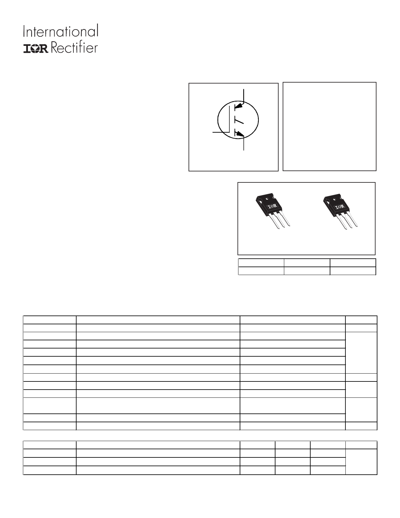
INSULATED GATE BIPOLAR TRANSISTOR
Features
• Low VCE (ON) trench IGBT technology
• Low switching losses
• Maximum junction temperature 175 °C
• Square RBSOA
• 100% of the parts tested for ILM
• Positive VCE (ON) temperature co-efficient
• Tight parameter distribution
• Lead -Free
Benefits
• High efficiency in a wide range of applications
• Suitable for a wide range of switching frequencies due to
low VCE (ON) and low switching losses
• Rugged transient performance for increased reliability
• Excellent current sharing in parallel operation
Applications
• U.P.S
• Welding
• Solar inverter
• Induction heating
C
G
E
n-channel
PD - 96233A
IRG7PH42UPbF
IRG7PH42U-EP
VCES = 1200V
IC = 60A, TC = 100°C
TJ(max) =175°C
VCE(on) typ. = 1.7V
CC
GC E
TO-247AC
IRG7PH42UPbF
GC E
TO-247AD
IRG7PH42U-EP
G
Gate
C
Collector
E
Emitter
Absolute Maximum Ratings
Parameter
VCES
IC @ TC = 25°C
IC @ TC = 100°C
INOMINAL
ICM
ILM
VGE
PD @ TC = 25°C
PD @ TC = 100°C
TJ
TSTG
Collector-to-Emitter Voltage
Continuous Collector Current (Silicon Limited)
Continuous Collector Current (Silicon Limited)
Nominal Current
Pulse Collector Current, VGE = 15V
cClamped Inductive Load Current, VGE = 20V
Continuous Gate-to-Emitter Voltage
Maximum Power Dissipation
Maximum Power Dissipation
Operating Junction and
Storage Temperature Range
Soldering Temperature, for 10 sec.
Mounting Torque, 6-32 or M3 Screw
Thermal Resistance
RθJC (IGBT)
RθCS
RθJA
Parameter
fThermal Resistance Junction-to-Case-(each IGBT) TO-247AC
fThermal Resistance, Case-to-Sink (flat, greased surface)
Thermal Resistance, Junction-to-Ambient (typical socket mount)
1
Max.
1200
90g
60
30
90
120
±30
385
192
-55 to +175
300 (0.063 in. (1.6mm) from case)
10 lbf·in (1.1 N·m)
Min.
–––
–––
–––
Typ.
–––
0.24
40
Max.
0.39
–––
–––
Units
V
A
V
W
°C
Units
°C/W
www.irf.com
02/18/10
1 page 
IRG7PH42UPbF/IRG7PH42U-EP
120 7000
100
80
TJ = 25°C
TJ = 175°C
60
40
20
6000
5000
4000
3000
2000
1000
EON
EOFF
0
4 6 8 10
VGE, Gate-to-Emitter Voltage (V)
Fig. 12- Typ. Transfer Characteristics
VCE = 50V; tp = 20µs
12
1000
tdOFF
100
tR
10 tdON
tF
1
0 10 20 30 40 50 60
IC (A)
Fig. 14 - Typ. Switching Time vs. IC
TJ = 175°C; L = 200µH; VCE = 600V, RG = 10Ω; VGE = 15V
10000
0
0 10 20 30 40 50 60
IC (A)
Fig. 13 - Typ. Energy Loss vs. IC
TJ = 175°C; L = 200µH; VCE = 600V, RG = 10Ω; VGE = 15V
6000
5500
5000
4500
4000
3500
EON
EOFF
3000
2500
2000
1500
1000
0
25 50 75 100
Rg (Ω)
Fig. 15 - Typ. Energy Loss vs. RG
TJ = 175°C; L = 200µH; VCE = 600V, ICE = 30A; VGE = 15V
www.irf.com
1000
tdOFF
100 tF
tR
tdON
10
0 20 40 60 80 100
RG (Ω)
Fig. 16 - Typ. Switching Time vs. RG
TJ = 175°C; L = 200µH; VCE = 600V, ICE = 30A; VGE = 15V
5
5 Page | ||
| Páginas | Total 10 Páginas | |
| PDF Descargar | [ Datasheet G7PH42U-EP.PDF ] | |
Hoja de datos destacado
| Número de pieza | Descripción | Fabricantes |
| G7PH42U-EP | IRG7PH42U-EP | International Rectifier |
| Número de pieza | Descripción | Fabricantes |
| SLA6805M | High Voltage 3 phase Motor Driver IC. |
Sanken |
| SDC1742 | 12- and 14-Bit Hybrid Synchro / Resolver-to-Digital Converters. |
Analog Devices |
|
DataSheet.es es una pagina web que funciona como un repositorio de manuales o hoja de datos de muchos de los productos más populares, |
| DataSheet.es | 2020 | Privacy Policy | Contacto | Buscar |