|
|
|
PDF SI-8008HD Data sheet ( Hoja de datos )
| Número de pieza | SI-8008HD | |
| Descripción | DC-to-DC Step-Down Converter | |
| Fabricantes | Sanken | |
| Logotipo | ||
Hay una vista previa y un enlace de descarga de SI-8008HD (archivo pdf) en la parte inferior de esta página. Total 13 Páginas | ||
|
No Preview Available !
SI-8008HD
DC-to-DC Step-Down Converter
Features and Benefits
▪ 5.5 A output current supplied in a small, surface mount
power package
▪ High efficiency: 83% at VIN= 15 V, IO= 3.0 A,VO= 5 V
▪ Requires only seven external components (optional soft
start requires an additional capacitor)
▪ Oscillation circuit built-in (frequency 150 kHz typical)
▪ Constant-current mode overcurrent protection circuit and
overtemperature protection circuit built-in
▪ Soft start function built-in (can be implemented as an
on/off function; output-off state at low level)
▪ Low current consumption during output-off state
Package: TO263-5
Description
The SI-8008HD DC voltage regulator is a DC-to-DC buck
convertor that attains an oscillation frequency of 150 kHz,
and has an integrated miniaturized choke coil, allowing it to
serve as a small, high efficiency power supply in a compact
TO-263 package.
The internal switching regulator function provides high
efficiency switching regulation without any need for adjustment.
The device requires only six external support components. The
optional soft start function requires an additional capacitor.
Optional on/off control can be performed using a transistor.
The SI-8008HD includes overcurrent and overtemperature
protection circuits.
Applications include:
▪ DVD recorder
▪ FPD TV
▪ Telecommunications equipment
▪ Office automation equipment, such as printers
▪ On-board local power supply
▪ Output voltage regulator for second stage of SMPS
(switched mode power supply)
Not to scale
27469.059
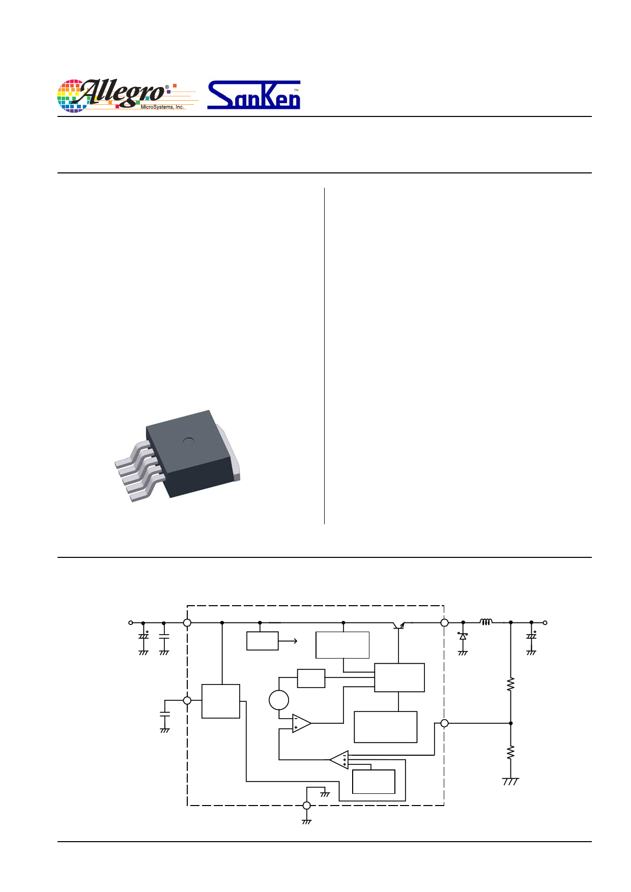
Functional Block Diagram
VIN 1 IN
C1 C4
PReg
Overcurrent
Protection
SW 2
L1
Di
FMB-G16L
(Sanken)
VOU
C2
5 SS On/Off
Soft Start
C3
Reset
Osc
Comparator
Error
Amplifier
Latch and
Driver
Overtemperature
Protection
ADJ 4
R1
R2
GND
3
Reference
Voltage
1 page 
SI-8008HD
DC-to-DC Step-Down Converter
Thermal Performance Characteristics
The application must be designed to ensure that the TJ(max)
of the device is not exceeded during operation. To do so, it is
necessary to determine values for maximum power dissipation,
PD(max), and ambient temperature, TA(max).
The relationships of TJ, PD, TA, and case temperature, TC, are as
shown in the following formulas:
PD =
TJ – TC
RθJC
and
PD =
TJ – TA
RθJA
PD can be calculated from input values:
.
where:
PD
= VO
⋅
I
O
⎜⎜⎝⎛
100
Hx
−
1⎟⎟⎠⎞
−
VF
⋅
I
O
⎜⎜⎝⎛1
−
VO
VIN
⎟⎟⎠⎞
VO is output voltage in V,
VIN is input supply voltage in V,
IO is output current in A,
ηx is IC efficiency in percent (varies with VIN and IO; refer to
efficiency performance curves for value), and
VF is forward voltage for the input diode, Di. In these tests, the
Sanken FMB-G16L was used, at 0.55 V. For application design,
obtain thermal data from the datasheet for the diode.
PD is substantially affected by the heat conductance properties of
the application, in particular any exposed copper area on the PCB
where the device is mounted. The relationships of PD, TA, and
copper area is represented in the Power Dissipation chart.
RθJA for a given copper area can be determined form the Device
Thermal Resistance chart. This can be substituted into the formula
above to determine the TJ (max) allowable in the application.
Generally, more than 10% to 20% derating is required.
Because the heat dissipation capacity of the copper area depends
substantively on how it is used in the actual application, thermal
characteristics of the application must be confirmed by testing.
TC is determined by connecting a thermocouple to the device as
shown here:
Thermocouple mount
at tab center
And analyzing the results using the following formula:
TJ = PD × RθJC + TC ,
for this device, RθJC is 3 °C/W.
Power Dissipation versus Ambient Temperature
TJ(max) = 125°C; Mounted on glass-epoxy PCB (40 mm × 40 mm),
with varying exposed copper areas
3.5
Cu Area: 1600 mm2
RθJA = 33.3°C/W
3.0
Cu Area: 800 mm2
RθJA = 37°C/W
2.5
2.0
Cu Area: 400 mm2
RθJA = 44°C/W
Cu Area: 100 mm2
1.5 RθJA = 53°C/W
1.0
0.5
0
–25
0
25 50 75 100 125
TA (°C)
Device Thermal Resistance versus Exposed Copper Area on PCB
Glass-epoxy PCB, 40 mm × 40 mm
55
50
45
40
35
30
0
200 400 600 800 1000 1200 1400 1600 1800
Copper Area (mm2)
Power Dissipation versus Output Current
10
9
8
7
VIN (V) 8
6 15
5 20
4 40
3
2
1
0
01 23456
IO(A)
Allegro MicroSystems, Inc.
115 Northeast Cutoff, Box 15036
Worcester, Massachusetts 01615-0036 (508) 853-5000
www.allegromicro.com
5
5 Page 
SI-8008HD
DC-to-DC Step-Down Converter
The products described herein are manufactured in Japan by Sanken Electric Co., Ltd. for sale by Allegro MicroSystems, Inc.
Sanken and Allegro reserve the right to make, from time to time, such departures from the detail specifications as may be required to permit im-
provements in the performance, reliability, or manufacturability of its products. Therefore, the user is cautioned to verify that the information in this
publication is current before placing any order.
The information included herein is believed to be accurate and reliable. Application and operation examples described in this document are given
for reference only and Sanken assumes no responsibility for any infringement of industrial property right, intellectual property rights or any other
rights of Sanken or any third party which may result from its use.
When using the products herein, the applicability and suitability of such products for the intended purpose shall be the users responsibility to
determine.
Although Sanken undertakes to enhance the quality and reliability of its products, the occurrence of failure and defect of semiconductor products
at a certain rate is inevitable.
Users of Sanken products are requested to take, at their own risk, preventative measures including safety design of the equipment or systems
against any possible injury, death, fires or damages to society due to device failure or malfunction.
Sanken products listed in this document are designed and intended for the use as components in general purpose electronic equipment or appara-
tus (home appliances, office equipment, telecommunication equipment, measuring equipment, etc.). When considering the use of Sanken products in
the applications where higher reliability is required (transportation equipment and its control systems, traffic signal control systems or equipment,
fire/crime alarm systems, various safety devices, etc.), please contact your nearest Sanken sales representative to discuss and obtain written confir-
mation of your specifications.
The use of Sanken products without the written consent of Sanken in the applications where extremely high reliability is required (aerospace equip-
ment, nuclear power control systems, life support systems, etc.) is strictly prohibited. Anti-radioactive ray design is not considered for the products
listed herein.
Copyright © 2007 Allegro MicroSystems, Inc.
This datasheet is based on Sanken datasheet SSJ-03118
For the latest version of this document, visit our website:
www.allegromicro.com
Allegro MicroSystems, Inc.
115 Northeast Cutoff, Box 15036
Worcester, Massachusetts 01615-0036 (508) 853-5000
www.allegromicro.com
11
11 Page | ||
| Páginas | Total 13 Páginas | |
| PDF Descargar | [ Datasheet SI-8008HD.PDF ] | |
Hoja de datos destacado
| Número de pieza | Descripción | Fabricantes |
| SI-8008HD | DC-to-DC Step-Down Converter | Sanken |
| SI-8008HFE | DC-to-DC Step-Down Converter | Sanken |
| Número de pieza | Descripción | Fabricantes |
| SLA6805M | High Voltage 3 phase Motor Driver IC. |
Sanken |
| SDC1742 | 12- and 14-Bit Hybrid Synchro / Resolver-to-Digital Converters. |
Analog Devices |
|
DataSheet.es es una pagina web que funciona como un repositorio de manuales o hoja de datos de muchos de los productos más populares, |
| DataSheet.es | 2020 | Privacy Policy | Contacto | Buscar |