|
|
|
PDF MAX5082 Data sheet ( Hoja de datos )
| Número de pieza | MAX5082 | |
| Descripción | 1.5A / 40V / MAXPower Step-Down DC-DC Converters | |
| Fabricantes | Maxim Integrated Products | |
| Logotipo | ||
Hay una vista previa y un enlace de descarga de MAX5082 (archivo pdf) en la parte inferior de esta página. Total 18 Páginas | ||
|
No Preview Available !
19-3657; Rev 0; 5/05
www.DataSheet4U.com
1.5A, 40V, MAXPower Step-Down
DC-DC Converters
General Description
The MAX5082/MAX5083 are 250kHz PWM step-down
DC-DC converters with an on-chip, 0.3Ω high-side
switch. The input voltage range is 4.5V to 40V for the
MAX5082 and 7.5V to 40V for the MAX5083. The output
is adjustable from 1.23V to 32V and can deliver up to
1.5A of load current.
Both devices utilize a voltage-mode control scheme for
good noise immunity in the high-voltage switching envi-
ronment and offer external compensation allowing for
maximum flexibility with a wide selection of inductor val-
ues and capacitor types. The switching frequency is
internally fixed at 250kHz and can be synchronized to
an external clock signal through the SYNC input. Light
load efficiency is improved by automatically switching
to a pulse-skip mode.
All devices include programmable undervoltage lock-
out and soft-start. Protection features include cycle-by-
cycle current limit, hiccup-mode output short-circuit
protection, and thermal shutdown. Both devices are
available in a space-saving, high-power (2.7W), 16-pin
TQFN package and are rated for operation over the
-40°C to +125°C temperature range.
Applications
FireWire® Power Supplies
Distributed Power
Automotive
Industrial
Features
♦ 4.5V to 40V (MAX5082) or 7.5V to 40V (MAX5083)
Input Voltage Range
♦ 1.5A Output Current
♦ VOUT Range From 1.23V to 32V
♦ Internal High-Side Switch
♦ Fixed 250kHz Internal Oscillator
♦ Automatic Switchover to Pulse-Skip Mode at
Light Loads
♦ External Frequency Synchronization
♦ Thermal Shutdown and Short-Circuit Protection
♦ Operates Over the -40°C to +125°C Temperature
Range
♦ Space-Saving (5mm x 5mm) High-Power 16-Pin
TQFN Package
Ordering Information
PART
MAX5082ATE
MAX5083ATE
*EP = Exposed pad.
TEMP RANGE
-40°C to +125°C
-40°C to +125°C
PIN-PACKAGE
16 TQFN-EP*
16 TQFN-EP*
FireWire is a registered trademark of Apple Computer, Inc.
Pin Configurations appear at end of data sheet.
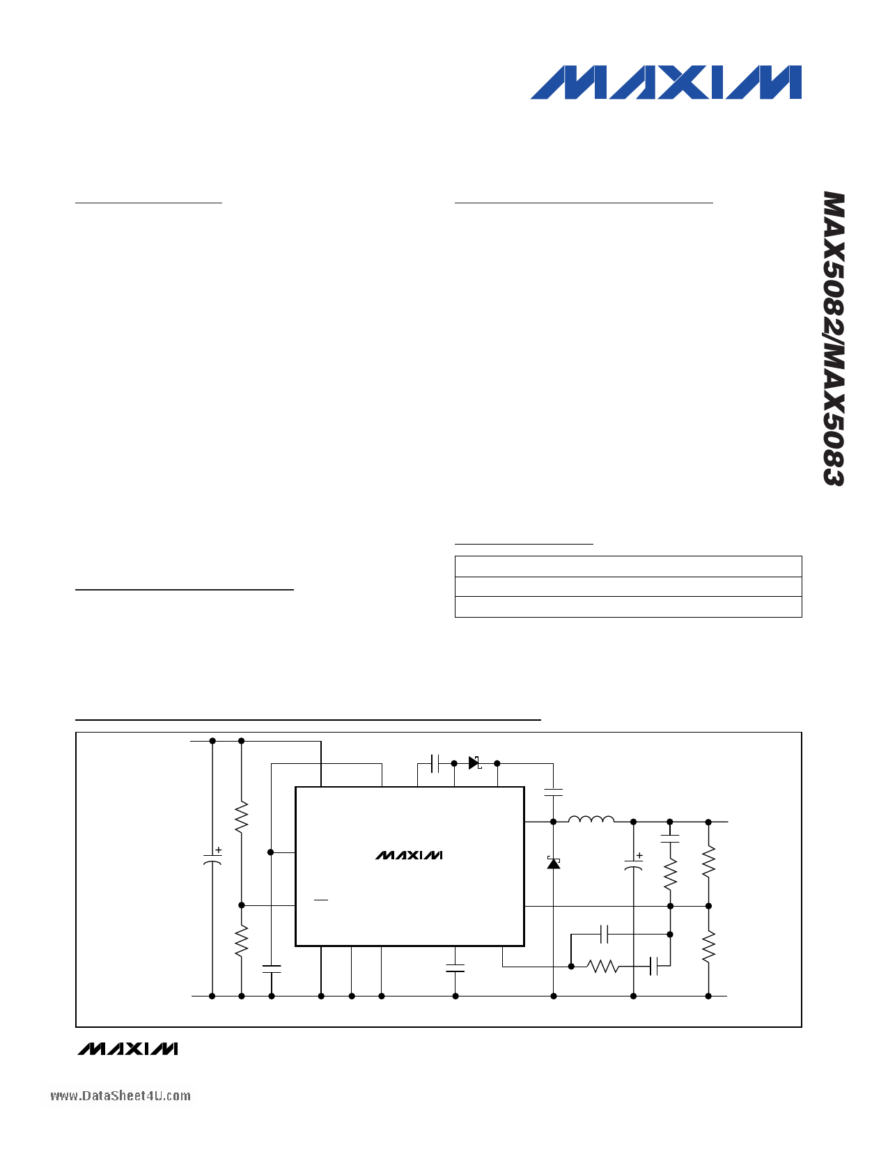
Typical Operating Circuits
VIN
4.5V TO 40V
CF D1
R1
C1
IN
REG
DVREG C-
C+
BST
LX
MAX5082
CBST
L1
D2
VOUT
C6
C5
R6
R3
ON/OFF
R2 SYNC SGND PGND
C2
PGND
Typical Operating Circuits continued at end of data sheet.
FB
SS COMP
CSS
C8
R5 C7
R4
PGND
________________________________________________________________ Maxim Integrated Products 1
For pricing, delivery, and ordering information, please contact Maxim/Dallas Direct! at
1-888-629-4642, or visit Maxim’s website at www.maxim-ic.com.
1 page 
www.DataSheet4U.com
1.5A, 40V, MAXPower Step-Down
DC-DC Converters
Typical Operating Characteristics (continued)
(VIN = 12V, see Figure 5 (MAX5082) and Figure 6 (MAX5083), TA = +25°C, unless otherwise noted.)
100
98
96
94
92
90
88
86
84
82
80
0
MAXIMUM DUTY CYCLE
vs. INPUT VOLTAGE (MAX5083)
5 10 15 20 25 30 35
INPUT VOLTAGE (V)
40
OPEN-LOOP GAIN/PHASE vs. FREQUENCY
MAX5082 toc10
100 175
80
60
40
20
PHASE
0
GAIN 150
125
100
75
-20 50
0 0.001 0.01 0.1 1 10 100 1000 10,000
FREQUENCY (kHz)
OUTPUT CURRENT LIMIT
vs. INPUT VOLTAGE
3.0
MAX5082
2.9
2.8 TA = +25°C
TA = -40°C
2.7
2.6
2.5 TA = +135°C
2.4 TA = +85°C
2.3
2.2
2.1
2.0
0
OUTPUT IS
PULSED WITH 3% DUTY CYCLE
5 10 15 20 25 30
INPUT VOLTAGE (V)
35
40
TURN-ON/OFF WAVEFORM
MAX5082/3 toc11a
ILOAD = 1A
VON/OFF
2V/div
TURN-ON/OFF WAVEFORM
MAX5082/3 toc11b
ILOAD = 100mA
VON/OFF
2V/div
VOUT
2V/div
VOUT
2V/div
2ms/div
2ms/div
OUTPUT VOLTAGE vs. TEMPERATURE
3.40
MAX5082
3.38
3.36
3.34 ILOAD = 0A
3.32
3.30
3.28
3.26 ILOAD = 1A
3.24
3.22
3.20
-40 -15 10 35 60 85 110 135
TEMPERATURE (°C)
EFFICIENCY vs. LOAD CURRENT
100
VIN = 4.5V,
90 VOUT = 3.3V
80
70
60
50
40
30
20
0
0.001
VIN = 7.5V,
VOUT = 3.3V
VIN = 12V,
VOUT = 3.3V
VIN = 24V,
VOUT = 3.3V
VIN = 40V,
VOUT = 3.3V
MAX5082
0.01 0.1
1
LOAD CURRENT (A)
10
_______________________________________________________________________________________ 5
5 Page 
www.DataSheet4U.com
1.5A, 40V, MAXPower Step-Down
DC-DC Converters
R4 = R3
⎡
⎢
⎣
VOUT
VFB
⎤
− 1⎥
⎦
where VFB = 1.23V.
Inductor Selection
Three key inductor parameters must be specified for
operation with the MAX5082/MAX5083: inductance
value (L), peak inductor current (IPEAK), and inductor
saturation current (ISAT). The minimum required induc-
tance is a function of operating frequency, input-to-out-
put voltage differential, and the peak-to-peak inductor
current (∆IP-P). Higher ∆IP-P allows for a lower inductor
value while a lower ∆IP-P requires a higher inductor
value. A lower inductor value minimizes size and cost
and improves large-signal and transient response, but
reduces efficiency due to higher peak currents and
higher peak-to-peak output voltage ripple for the same
output capacitor. On the other hand, higher inductance
increases efficiency by reducing the ripple current.
Resistive losses due to extra wire turns can exceed the
benefit gained from lower ripple current levels especial-
ly when the inductance is increased without also allow-
ing for larger inductor dimensions. A good compromise
is to choose ∆IP-P equal to 40% of the full load current.
Calculate the inductor using the following equation:
L = VOUT(VIN − VOUT)
VIN × fSW × ∆IP-P
VIN and VOUT are typical values so that efficiency is opti-
mum for typical conditions. The switching frequency
(fSW) is fixed at 250kHz or can vary between 150kHz and
350kHz when synchronized to an external clock (see the
Oscillator/Synchronization Input (SYNC) section). The
peak-to-peak inductor current, which reflects the peak-to-
peak output ripple, is worst at the maximum input voltage.
See the Output Capacitor Selection section to verify that
the worst-case output ripple is acceptable. The inductor
saturating current (ISAT) is also important to avoid run-
away current during continuous output short circuit.
Select an inductor with an ISAT specification higher than
the maximum peak current limit of 3.5A.
Input Capacitor Selection
The discontinuous input current of the buck converter
causes large input ripple currents and therefore the
input capacitor must be carefully chosen to keep the
input voltage ripple within design requirements. The
input voltage ripple is comprised of ∆VQ (caused by the
capacitor discharge) and ∆VESR (caused by the ESR of
the input capacitor). The total voltage ripple is the sum
of ∆VQ and ∆VESR. Calculate the input capacitance and
ESR required for a specified ripple using the following
equations:
ESR =
∆VESR
⎛⎝⎜IOUT_MAX +
∆IP-P
2
⎞
⎠⎟
where
CIN
=
IOUT_MAX × D(1 −
∆VQ × fSW
D)
∆IP-P
=
(VIN − VOUT) × VOUT
VIN × fSW × L
and
D = VOUT
VIN
IOUT_MAX is the maximum output current, D is the duty
cycle, and fSW is the switching frequency.
The MAX5082/MAX5083 includes internal and external
UVLO hysteresis and soft-start to avoid possible unin-
tentional chattering during turn-on. However, use a bulk
capacitor if the input source impedance is high. Use
enough input capacitance at lower input voltages to
avoid possible undershoot below the undervoltage
lockout threshold during transient loading.
Output Capacitor Selection
The allowable output voltage ripple and the maximum
deviation of the output voltage during load steps deter-
mine the output capacitance and its ESR. The output
ripple is mainly composed of ∆VQ (caused by the
capacitor discharge) and ∆VESR (caused by the volt-
age drop across the equivalent series resistance of the
output capacitor). The equations for calculating the
peak-to-peak output voltage ripple are:
∆VQ
=
16
×
∆IP- P
COUT ×
fSW
∆VESR = ESR × ∆IP-P
Normally, a good approximation of the output voltage
ripple is ∆VRIPPLE ≈ ∆VESR + ∆VQ. If using ceramic
capacitors, assume the contribution to the output volt-
age ripple from ESR and the capacitor discharge to be
______________________________________________________________________________________ 11
11 Page | ||
| Páginas | Total 18 Páginas | |
| PDF Descargar | [ Datasheet MAX5082.PDF ] | |
Hoja de datos destacado
| Número de pieza | Descripción | Fabricantes |
| MAX5080 | 1A / 40V / MAXPower Step-Down DC-DC Converters | Maxim Integrated Products |
| MAX5081 | 1A / 40V / MAXPower Step-Down DC-DC Converters | Maxim Integrated Products |
| MAX5082 | 1.5A / 40V / MAXPower Step-Down DC-DC Converters | Maxim Integrated Products |
| MAX5083 | 1.5A / 40V / MAXPower Step-Down DC-DC Converters | Maxim Integrated Products |
| Número de pieza | Descripción | Fabricantes |
| SLA6805M | High Voltage 3 phase Motor Driver IC. |
Sanken |
| SDC1742 | 12- and 14-Bit Hybrid Synchro / Resolver-to-Digital Converters. |
Analog Devices |
|
DataSheet.es es una pagina web que funciona como un repositorio de manuales o hoja de datos de muchos de los productos más populares, |
| DataSheet.es | 2020 | Privacy Policy | Contacto | Buscar |