|
|
|
PDF LOG100 Data sheet ( Hoja de datos )
| Número de pieza | LOG100 | |
| Descripción | Precision LOGARITHMIC AND LOG RATIO AMPLIFIER | |
| Fabricantes | Burr-Brown Corporation | |
| Logotipo | ||
Hay una vista previa y un enlace de descarga de LOG100 (archivo pdf) en la parte inferior de esta página. Total 9 Páginas | ||
|
No Preview Available !
® LOG100
Precision
LOGARITHMIC AND LOG RATIO AMPLIFIER
FEATURES
q ACCURACY
0.37% FSO max Total Error
Over 5 Decades
q LINEARITY
0.1% max Log Conformity
Over 5 Decades
q EASY TO USE
Pin-selectable Gains
Internal Laser-trimmed Resistors
q WIDE INPUT DYNAMIC RANGE
6 Decades, 1nA to 1mA
q HERMETIC CERAMIC DIP
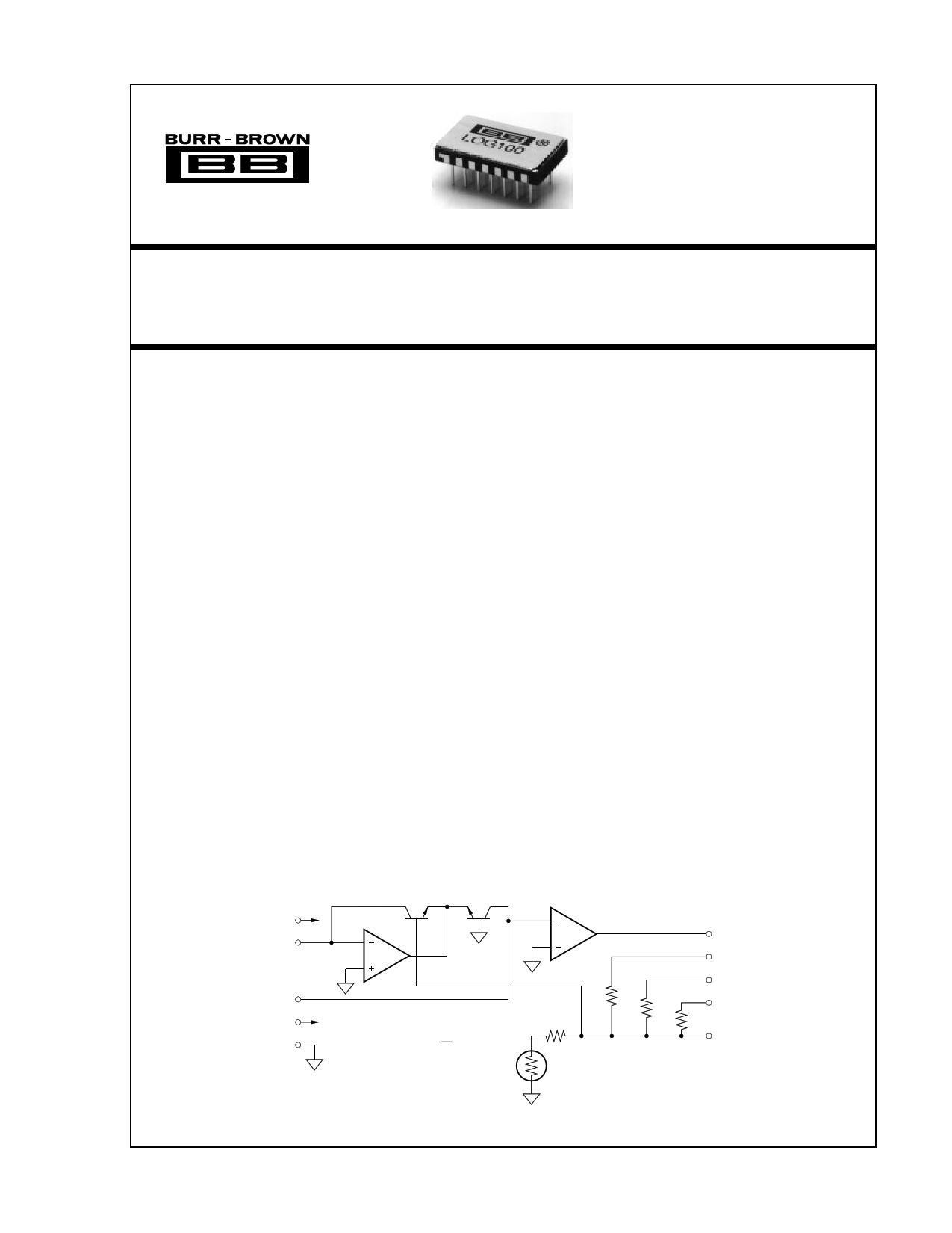
DESCRIPTION
The LOG100 uses advanced integrated circuit tech-
nologies to achieve high accuracy, ease of use, low
cost, and small size. It is the logical choice for your
logarithmic-type computations. The amplifier has guar-
anteed maximum error specifications over the full six-
decade input range (1nA to 1mA) and for all possible
combinations of I1 and I2. Total error is guaranteed so
that involved error computations are not necessary.
The circuit uses a specially designed compatible thin-
film monolithic integrated circuit which contains am-
plifiers, logging transistors, and low drift thin-film
9
–VCC
1
I1
Q1
A1
Q2
14
I2
6
+VCC
10
Com
VOUT = K LOG
I1
I2
APPLICATIONS
q LOG, LOG RATIO AND ANTILOG
COMPUTATIONS
q ABSORBANCE MEASUREMENTS
q DATA COMPRESSION
q OPTICAL DENSITY MEASUREMENTS
q DATA LINEARIZATION
q CURRENT AND VOLTAGE INPUTS
resistors. The resistors are laser-trimmed for maxi-
mum precision. FET input transistors are used for the
amplifiers whose low bias currents (1pA typical) per-
mit signal currents as low as 1nA while maintaining
guaranteed total errors of 0.37% FSO maximum.
Because scaling resistors are self-contained, scale
factors of 1V, 3V or 5V per decade are obtained
simply by pin selections. No other resistors are re-
quired for log ratio applications. The LOG100 will
meet its guaranteed accuracy with no user trimming.
Provisions are made for simple adjustments of scale
factor, offset voltage, and bias current if enhanced
performance is desired.
A2
270Ω
220Ω
7.5kΩ
24kΩ
7
VOUT
3
K=1
4
K=3
5
K=5
39kΩ
Scale
Factor
2 Trim
Resistor values nominal only;
laser-trimmed for precision gain.
International Airport Industrial Park • Mailing Address: PO Box 11400 • Tucson, AZ 85734 • Street Address: 6730 S. Tucson Blvd. • Tucson, AZ 85706
Tel: (520) 746-1111 • Twx: 910-952-1111 • Cable: BBRCORP • Telex: 066-6491 • FAX: (520) 889-1510 • Immediate Product Info: (800) 548-6132
© 1981 Burr-Brown Corporation
PDS-437E
Printed in U.S.A. January, 1995
1 page 
THEORY OF OPERATION
The base-emitter voltage of a bipolar transistor is
VBE = VT l n
IC
IS
KT
where: VT = q
(1)
K = Boltzman’s constant = 1.381 x 10⁻²³
T = Absolute temperature in degrees Kelvin
q = Electron charge = 1.602 x 10⁻¹⁹ Coulombs
IC = Collector current
IS = Reverse saturation current
From the circuit in Figure 1, we see that
VOUT' = VBE1 – VBE2
Substituting (1) into (2) yields
(2)
VOUT' = VT1 l n
I1
IS1
– VT2
ln
I1
IS2
(3)
If the transistors are matched and isothermal and VT1 = VT2,
then (3) becomes:
VOUT' = VT [ l n
I1 – l n
IS
I2 ]
I
S
VOUT' = VT ln
I1
I
and since
2
(4)
(5)
ln x = 2.3 log10 x
I
VOUT' = n VT log
1
I
2
where n = 2.3
(6)
(7)
(8)
also
VOUT = VOUT'
R1 + R2
R1
(9)
=
R1 + R2
R
n VT log
I1
I
or 1
2
(10)
VOUT = K log
I1
I2
(11)
It should be noted that the temperature dependance associ-
ated with VT = KT/q is compensated by making R1 a
temperature sensitive resistor with the required positive
temperature coefficient.
DEFINITION OF TERMS
TRANSFER FUNCTION
The ideal transfer function is VOUT = K log
where:
I1
I
2
K = the scale factor with units of volts/decade
I1 = numerator input current
I2 = denominator input current.
ACCURACY
Accuracy considerations for a log ratio amplifier are some-
what more complicated than for other amplifiers. The reason
is that the transfer function is nonlinear and has two inputs,
each of which can vary over a wide dynamic range. The
accuracy for any combination of inputs is determined from
the total error specification.
10
K=5
K=3
8
6
4 K=1
2 1nA 10nA 100nA
I1
0
1µA 10µA 100µA 1mA
–2
–4
–6
VOUT = K LOG
I1
I2
–8 I2 = 1µA
–10 Fixed value of I2.
FIGURE 2. Transfer Function with Varying K and I1.
I1
I1
Q1 –
– Q2
++
VBE1 VBE2
I2
A2
VOUT
A1
VOUT = K LOG
I1
I2
R2
I2 VOUT
R1
FIGURE 1. Simplified Model of Log Amplifier.
10
I2 = 10nA
I2 = 1µA
8
6
4 I2 = 100µA
2 1nA 10nA 100nA 1µA 10µA 100µA 1mA I1
0
–2
–4
–6
VOUT = K LOG
I1
I2
K=3
–8
Fixed value of K.
–10
FIGURE 3. Transfer Function with Varying I and I .
21
®
5 LOG100
5 Page | ||
| Páginas | Total 9 Páginas | |
| PDF Descargar | [ Datasheet LOG100.PDF ] | |
Hoja de datos destacado
| Número de pieza | Descripción | Fabricantes |
| LOG100 | Precision LOGARITHMIC AND LOG RATIO AMPLIFIER | Burr-Brown Corporation |
| LOG100 | Precision Logarithmic and Log Ratio Amplifier | Texas Instruments |
| LOG100JP | Precision LOGARITHMIC AND LOG RATIO AMPLIFIER | Burr-Brown Corporation |
| LOG101 | Precision LOGARITHMIC AND LOG RATIO AMPLIFIER | Burr-Brown Corporation |
| Número de pieza | Descripción | Fabricantes |
| SLA6805M | High Voltage 3 phase Motor Driver IC. |
Sanken |
| SDC1742 | 12- and 14-Bit Hybrid Synchro / Resolver-to-Digital Converters. |
Analog Devices |
|
DataSheet.es es una pagina web que funciona como un repositorio de manuales o hoja de datos de muchos de los productos más populares, |
| DataSheet.es | 2020 | Privacy Policy | Contacto | Buscar |