|
|
|
PDF X93256 Data sheet ( Hoja de datos )
| Número de pieza | X93256 | |
| Descripción | Dual Digitally Controlled Potentiometers | |
| Fabricantes | Intersil Corporation | |
| Logotipo | ||
Hay una vista previa y un enlace de descarga de X93256 (archivo pdf) en la parte inferior de esta página. Total 9 Páginas | ||
|
No Preview Available !
®
Data Sheet
March 24, 2006
X93256
FN8188.1
Dual Digitally Controlled Potentiometers
(XDCPs™)
FEATURES
• Dual solid-state potentiometers
• Individual Up/Down interfaces
• 32 wiper tap points per potentiometer
—Wiper position stored in nonvolatile memory
and recalled on power-up
• 31 resistive elements per potentiometer
—Temperature compensated
—Maximum resistance tolerance of ± 25%
—Terminal voltage, 0 to VCC
• Low power CMOS
—VCC = 2.7 V - 5.5 V.
—Active current, 200µA typical per potentiometer
—Standby current, 4µA max per potentiometer
• High reliability
—Endurance 200,000 data changes per bit
—Register data retention, 100 years
• RTOTAL value = 12.5kΩ, 50kΩ
• Packages
—14 Ld TSSOP
www.DataSheet4U.com
• Pb-free plus anneal available (RoHS compliant)
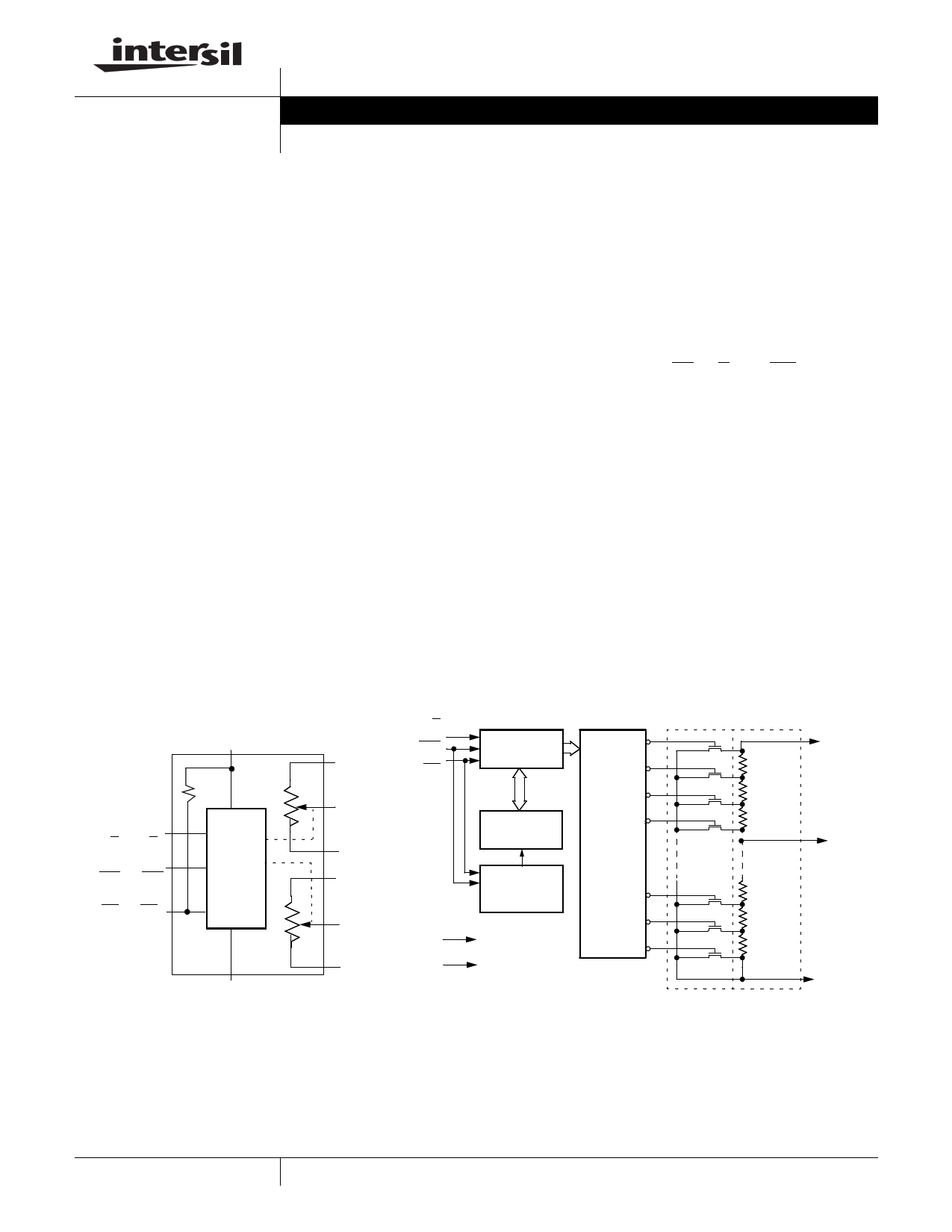
BLOCK DIAGRAM
General Description
VCC (Supply Voltage)
30K
Up/Down
(U/D1 & U/D2)
Increment
(INC1 & INC2)
Device Select
(CS1 & CS2)
Control
and
Memory
VSS (Ground)
RH1
RW1
RL1
RH2
RW2
RL2
U/D1
INC1
CS1
VCC
VSS
DESCRIPTION
The Intersil X93256 is a dual digitally controlled
potentiometer (XDCP). The device consists of two
resistor arrays, wiper switches, a control section, and
nonvolatile memory. The wiper positions are controlled
by individual Up/Down interfaces.
A potentiometer is implemented by a resistor array
composed of 31 resistive elements and a wiper switching
network. The position of each wiper element is controlled
by a set of independent CS, U/D, and INC inputs. The
position of the wiper can be stored in nonvolatile memory
and then be recalled upon a subsequent power-up
operation.
Each potentiometer is connected as a three-terminal
variable resistor and can be used in a wide variety of
applications including:
– Bias and Gain Control
– LCD Contrast Adjustment
Detailed Single Potentiometer Description
5-Bit
Up/Down
Counter
5-Bit
Nonvolatile
Memory
Store and
Control
Recall
Circuitry
31
30
29
28
One
of
Thirty
Two
Decoder
2
1
0
RH1
Transfer
Gates
Resistor
Array
RW
RL1
1
CAUTION: These devices are sensitive to electrostatic discharge; follow proper IC Handling Procedures.
1-888-INTERSIL or 1-888-468-3774 | Intersil (and design) is a registered trademark of Intersil Americas Inc.
XDCP is a trademark of Intersil Americas Inc. Copyright Intersil Americas Inc. 2005-2006. All Rights Reserved
All other trademarks mentioned are the property of their respective owners.
1 page 
X93256
D.C. OPERATING CHARACTERISTICS (Over recommended operating conditions unless otherwise specified.)
Symbol
Parameter
ICC1 VCC active current (Increment)
ICC2
VCC active current (Store)
(EEPROM Store)
ISB Standby supply current
ILI
ILI
ILI
ILI
VIH
VIL
CIN(5)(7)
CS input leakage current
CS input leakage current
CS input leakage current
INC, U/D input leakage current
CS, INC, U/D input HIGH voltage
CS, INC, U/D input LOW voltage
CS, INC, U/D input capacitance
Min.
Limits
Typ.(4)
50
Max.
250
200 300
600
1400
1
4
±1
60 100 150
120 200
250
±1
VCC x 0.7
-0.5
VCC + 0.5
VCC x 0.1
10
Unit
µA
µA
µA
µA
µA
µA
µA
µA
µA
V
V
pF
Test Conditions
CS = VIL, U/D = VIL or VIH and INC
= 0.4V @ max. tCYC VCC = 3V
CS = VIL, U/D = VIL or VIH and INC
= 0.4V @ max. tCYC VCC = 5V
CS = VIH, U/D = VIL or VIH and INC
= VIH @ max. tWR VCC = 3V
CS = VIH, U/D = VIL or VIH and INC
= VIH @ max. tWR VCC = 5V
CS = VCC - 0.3V, U/D and INC =
VSS or VCC - 0.3V VCC = 3V
CS = VCC - 0.3V, U/D and INC =
VSS or VCC - 0.3V VCC = 5V
VIN = VCC (5)
VCC = 3V, CS = 0 (5)
VCC = 5V, CS = 0 (5)
VIN = VSS to VCC (5)
(5)
(5)
fV=CC1M=H3zV(,6V) IN = VSS, TA = 25°C,
ENDURANCE AND DATA RETENTION
Parameter
Minimum endurance
Data retention
Min.
200,000
100
Unit
Data changes per bit
Years
Test Circuit #1
Test Point
VH/RH
Circuit #2 SPICE Macro Model
RTOTAL
RH
CH
CW CL RL
10pF
10pF
25pF
A.C. CONDITIONS OF TEST
Input pulse levels
Input rise and fall times
Input reference levels
0V to 3V
10ns
1.5V
5 FN8188.1
March 24, 2006
5 Page | ||
| Páginas | Total 9 Páginas | |
| PDF Descargar | [ Datasheet X93256.PDF ] | |
Hoja de datos destacado
| Número de pieza | Descripción | Fabricantes |
| X93254 | Dual Digitally Controlled Potentiometers | Intersil Corporation |
| X93255 | Dual Digitally Controlled Potentiometers | Intersil Corporation |
| X93256 | Dual Digitally Controlled Potentiometers | Intersil Corporation |
| Número de pieza | Descripción | Fabricantes |
| SLA6805M | High Voltage 3 phase Motor Driver IC. |
Sanken |
| SDC1742 | 12- and 14-Bit Hybrid Synchro / Resolver-to-Digital Converters. |
Analog Devices |
|
DataSheet.es es una pagina web que funciona como un repositorio de manuales o hoja de datos de muchos de los productos más populares, |
| DataSheet.es | 2020 | Privacy Policy | Contacto | Buscar |