|
|
|
PDF X9221A Data sheet ( Hoja de datos )
| Número de pieza | X9221A | |
| Descripción | Dual Digitally Controlled Potentiometer | |
| Fabricantes | Intersil Corporation | |
| Logotipo | ||
1. X9221A Hay una vista previa y un enlace de descarga de X9221A (archivo pdf) en la parte inferior de esta página. Total 15 Páginas | ||
|
No Preview Available !
®
Data Sheet
X9221A
64 Taps, 2-Wire Serial Bus
August 30, 2006
FN8163.2
Dual Digitally Controlled Potentiometer
(XDCP™)
FEATURES
• Two XDCPs in one package
• 2-wire serial interface
• Register oriented format, 8 registers total
—Directly write wiper position
—Read wiper position
—Store as many as four positions per pot
• Instruction format
—Quick transfer of register contents to resistor
array
• Direct write cell
—Endurance–100,000 writes per bit per register
• Resistor array values
—2kΩ, 10kΩ, 50kΩ
• Resolution: 64 taps each pot
• 20 Ld plastic DIP and 20 Ld SOIC packages
• Pb-free plus anneal available (RoHS compliant)
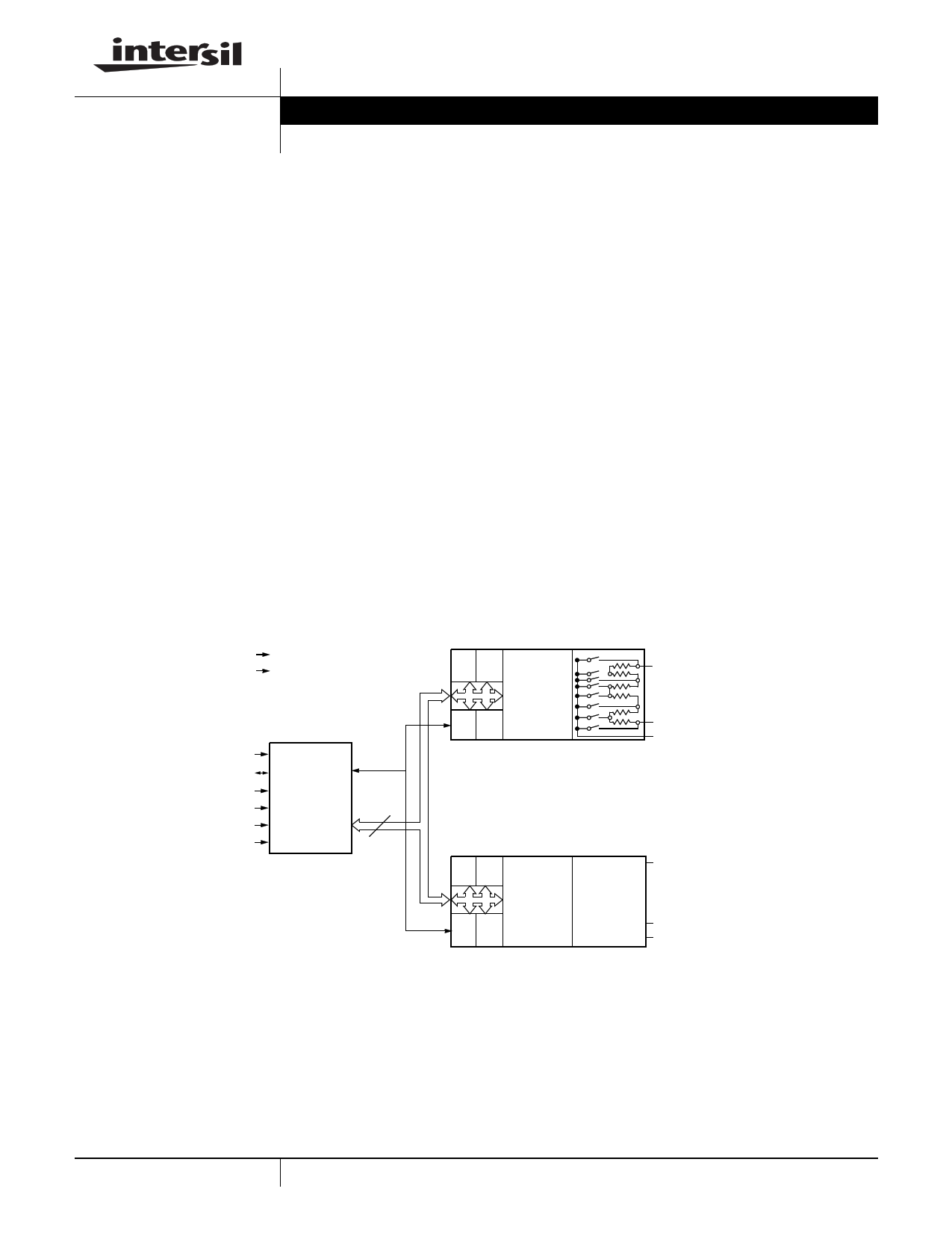
DESCRIPTION
The X9221A integrates two digitally controlled potenti-
ometers (XDCP) on a monolithic CMOS integrated
microcircuit.
The digitally controlled potentiometer is implemented
using 63 resistive elements in a series array. Between
each element are tap points connected to the wiper
terminal through switches. The position of the wiper on
the array is controlled by the user through the 2-wire
bus interface. Each potentiometer has associated with
it a volatile Wiper Counter Register (WCR) and 2 non-
volatile Data Registers (DR0:DR1) that can be directly
written to and read by the user. The contents of the
WCR controls the position of the wiper on the resistor
array through the switches. Power up recalls the con-
tents of DR0 to the WCR.
The XDCP can be used as a three-terminal potentiom-
eter or as a two-terminal variable resistor in a wide
variety of applications including control, parameter
adjustments, and signal processing.
BLOCK DIAGRAM
www.DataSheet4U.com
VCC
VSS
SCL
SDA
A0
A1
A2
A3
Interface
and
Control
Circuitry
8
Data
Pot 0
R0 R1
R2 R3
Wiper
Counter
Register
(WCR)
VH0/RH0
VL0/RL0
VW0/RW0
R0 R1
R2 R3
Wiper
Counter
Register
(WCR)
Register
Array
Pot 1
VH1/RH1
VL1/RL1
VW1/RW1
1 CAUTION: These devices are sensitive to electrostatic discharge; follow proper IC Handling Procedures.
1-888-INTERSIL or 1-888-468-3774 | Intersil (and design) is a registered trademark of Intersil Americas Inc.
XDCP is a trademark of Intersil Americas Inc. Copyright Intersil Americas Inc. 2005-2006. All Rights Reserved
All other trademarks mentioned are the property of their respective owners.
1 page 
X9221A
tuning capability to the host. For each SCL clock pulse
(tHIGH) while SDA is HIGH, the selected wiper will
move one resistor segment towards the VH/RH termi-
nal. Similarly, for each SCL clock pulse while SDA is
Figure 3. Two-Byte Command Sequence
LOW, the selected wiper will move one resistor seg-
ment towards the VL/RL terminal. A detailed illustra-
tion of the sequence and timing for this operation are
shown in Figures 5 and 6 respectively.
SCL
SDA
S 0 1 0 1 A3 A2 A1 A0 A I3 I2 I1 I0 0 P0 R1 R0 A S
TC
CT
AK
KO
RP
T
Figure 4. Three-Byte Command Sequence
SCL
SDA
S 0 1 0 1 A3 A2 A1 A0 A I3 I2 I1 I0 0 P0 R1 R0 A 0 0 D5 D4 D3 D2 D1 D0 A S
T
A
R
C
K
C
K
C
K
T
O
P
T
Figure 5. Increment/Decrement Command Sequined
e
SCL
SDA
XX
S 0 1 0 1 A3 A2 A1 A0 A I3 I2 I1 I0 0 P0 R1 R0 A I I
T
A
C
K
C
K
N
C
N
C
R
T
12
ID
NE
CC
n1
DS
ET
CO
nP
5 FN8163.2
August 30, 2006
5 Page 
X9221A
A.C. CONDITIONS OF TEST
Input pulse levels
Input rise and fall times
Input and output timing levels
VCC x 0.1 to VCC x 0.9
10ns
VCC x 0.5
SYMBOL TABLE
WAVEFORM
INPUTS
Must be
steady
May change
from LOW
to HIGH
May change
from HIGH
to LOW
Don’t Care:
Changes
Allowed
N/A
OUTPUTS
Will be
steady
Will change
from LOW
to HIGH
Will change
from HIGH
to LOW
Changing:
State Not
Known
Center Line
is High
Impedance
Equivalent A.C. Test Circuit
5V
1533Ω
SDA Output
100pF
Circuit #3 SPICE Macro Model
Macro Model
RH
RTOTAL
RL
CH CL
10pF
CW 10pF
25pF
RW
Guidelines for Calculating Typical Values of Bus
Pull-Up Resistors
120
100
RMIN
=
VCC MAX
IOL MIN
=1.8kΩ
80 RMAX =CtBRUS
60
Max.
Resistance
40
20 Min.
Resistance
0
0 20 40 60
80 100 120
Bus Capacitance (pF)
11 FN8163.2
August 30, 2006
11 Page | ||
| Páginas | Total 15 Páginas | |
| PDF Descargar | [ Datasheet X9221A.PDF ] | |
Hoja de datos destacado
| Número de pieza | Descripción | Fabricantes |
| X9221 | Dual E2POT Nonvolatile Digital Potentiometer | Xicor |
| X9221A | Dual Digitally Controlled Potentiometer | Intersil Corporation |
| X9221UP | Dual E2POT Nonvolatile Digital Potentiometer | Xicor |
| X9221UPI | Dual E2POT Nonvolatile Digital Potentiometer | Xicor |
| Número de pieza | Descripción | Fabricantes |
| SLA6805M | High Voltage 3 phase Motor Driver IC. |
Sanken |
| SDC1742 | 12- and 14-Bit Hybrid Synchro / Resolver-to-Digital Converters. |
Analog Devices |
|
DataSheet.es es una pagina web que funciona como un repositorio de manuales o hoja de datos de muchos de los productos más populares, |
| DataSheet.es | 2020 | Privacy Policy | Contacto | Buscar |