|
|
|
PDF EL1511 Data sheet ( Hoja de datos )
| Número de pieza | EL1511 | |
| Descripción | Medium Power Differential Line Driver | |
| Fabricantes | Intersil Corporation | |
| Logotipo | ||
Hay una vista previa y un enlace de descarga de EL1511 (archivo pdf) en la parte inferior de esta página. Total 18 Páginas | ||
|
No Preview Available !
®
Data Sheet
April 10, 2007
EL1511
FN7016.2
Medium Power Differential Line Driver
The EL1511 is a dual operational amplifier designed for
customer premise line driving in DMT ADSL solutions. This
device features a high drive capability of 360mA while
consuming only 7.5mA of supply current per amplifier and
operating from a single 5V to 15V supply. This driver
achieves a typical distortion of less than -85dBc, at 150kHz
into a 25Ω load. The EL1511 is available in the thermally-
enhanced 16 Ld SOIC (0.150") and a 16 Ld QFN (4x4mm)
packages. The EL1511 is specified for operation over the full
-40°C to +85°C temperature range. Electrical characteristics
are given for typical 15V supply operation.
The EL1511 has two control pins, C0 and C1, which allow
the selection of full IS power, 3/4-IS, 1/2-IS, and power-down
modes.
The EL1511 is ideal for ADSL, SDSL, and HDSL2 line
driving applications for single power supply, high voltage
swing, and low power.
The EL1511 maintains excellent distortion and load driving
capabilities even in the lowest power settings.
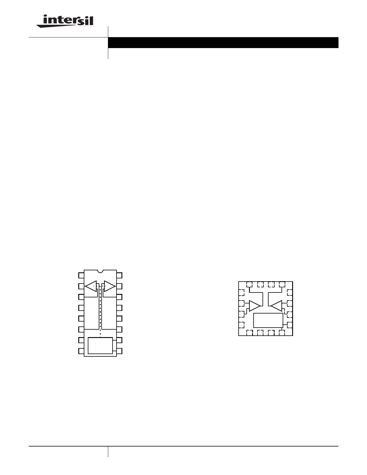
Pinoutswww.DataSheet4U.com
EL1511
[16 LD SO (0.150”)]
TOP VIEW
NC 1
VOUTA 2
VIN-A 3
16 VS+
+
-
+
-
15 VOUTB
14 VIN-B
GND* 4
13 GND*
GND* 5
12 GND*
VIN+A 6
11 VIN+B
GND 7
VS- 8
POWER
CONTROL
LOGIC
10 C1
9 C0
NOTE: * These GND pins are heat spreaders
Features
• Drives up to 360mA from a +15V supply
• 24VP-P differential output drive into 25Ω and 26VP-P
differential output drive into 100Ω
• -85dBc typical driver output distortion at full output at
150kHz
• Low quiescent current of 3.5mA per amplifier at 1/2-IS
current mode
• Disable down to 1.5mA
• Pb-free plus anneal available (RoHS compliant)
Applications
• ADSL CSA line driving
• ADSL full rate CPE line driving
• G.SHDSL, HDSL2 line driver
• Video distribution amplifier
• Video twisted-pair line driver
EL1511
(16 LD QFN)
TOP VIEW
NC 1
INA- 2
INA+ 3
GND 4
AMP
-A
+
AMP
B-
+
POWER
CONTROL
LOGIC
12 NC
11 INB-
10 INB+
9 C1
1 CAUTION: These devices are sensitive to electrostatic discharge; follow proper IC Handling Procedures.
1-888-INTERSIL or 1-888-468-3774 | Intersil (and design) is a registered trademark of Intersil Americas Inc.
Copyright Intersil Americas Inc. 2003, 2005, 2007. All Rights Reserved
All other trademarks mentioned are the property of their respective owners.
1 page 
Typical Performance Curves
28
VS=±6V
AV=10
24 RL=100Ω
20
16
RF=1.5kΩ
RF=1kΩ
RF=2kΩ
12
8
100K
1M 10M
FREQUENCY (Hz)
100M
FIGURE 1. DIFFERENTIAL FREQUENCY RESPONSE
(FULL POWER MODE)
EL1511
22
VS=±6V
AV=5
18 RL=100Ω
14
10
RF=1.5kΩ
RF=1kΩ
RF=2kΩ
6
2
100K
1M 10M
FREQUENCY (Hz)
100M
FIGURE 2. DIFFERENTIAL FREQUENCY RESPONSE
(FULL POWER MODE)
28
VS=±6V
AV=10
24 RL=100Ω
20
16
RF=1.5kΩ
RF=1kΩ
RF=2kΩ
12
8
100K
1M 10M
FREQUENCY (Hz)
100M
FIGURE 3. DIFFERENTIAL FREQUENCY RESPONSE
(3/4 POWER MODE)
22
VS=±6V
AV=5
18 RL=100Ω
14
10
RF=1kΩ
RF=1.5kΩ
RF=2kΩ
6
2
100K
1M 10M
FREQUENCY (Hz)
100M
FIGURE 4. DIFFERENTIAL FREQUENCY RESPONSE
(3/4 POWER MODE)
28
VS=±6V
AV=10
24 RL=100Ω
20
16
RF=1kΩ
RF=1.5kΩ
RF=2kΩ
12
8
100K
1M 10M
FREQUENCY (Hz)
100M
FIGURE 5. DIFFERENTIAL FREQUENCY RESPONSE
(1/2 POWER MODE)
22
VS=±6V
AV=5
18 RL=100Ω
14
10
RF=1kΩ
RF=1.5kΩ
RF=2kΩ
6
2
100K
1M 10M
FREQUENCY (Hz)
100M
FIGURE 6. DIFFERENTIAL FREQUENCY RESPONSE
(1/2 POWER MODE)
5 FN7016.2
April 10, 2007
5 Page 
Typical Performance Curves (Continued)
EL1511
0.14
0.12
0.1
VS=±6V
AV=2
RF=1.5kΩ
0.08
0.06
1/2 POWER
0.04
3/4 POWER
0.02
0
1
FULL POWER
1.5 2 2.5 3 3.5
NUMBER OF 150Ω LOADS
FIGURE 37. DIFFERENTIAL GAIN
4
CH 2
VOUT
CH 1
C0, C1
CH 1=2V/DIV
CH 2=2V/DIV
400ns/DIV
FIGURE 38. DISABLE TIME
0.15
0.14
0.13
VS=±6V
AV=2
RF=1.5kΩ
0.12
0.11
1/2 POWER
0.1 3/4 POWER
0.09
0.08
FULL POWER
0.07
1
1.5 2 2.5 3 3.5
NUMBER OF 150Ω LOADS
FIGURE 39. DIFFERENTIAL PHASE
4
CH 1=2V/DIV
CH 2=2V/DIV
CH 2
VOUT
CH 1
C0, C1
40ns/DIV
FIGURE 40. ENABLE TIME
16
IS+ (FULL POWER)
14 IS+ (3/4 POWER)
12
IS- (FULL POWER)
10
8 IS- (3/4 POWER)
6
4 IS+ (1/2 POWER) IS+ (1/2 POWER)
2
2 2.5 3 3.5 4 4.5 5 5.5 6 6.5 7 7.5
±VS (V)
FIGURE 41. SUPPLY CURRENT vs SUPPLY VOLTAGE
10
8
6
4
2
0
-2
-4
-6
-8
-10
-50
-25
IB-
IB+
0 25 50 75 100 125 150
DIE TEMPERATURE (°C)
FIGURE 42. INPUT BIAS CURRENT vs TEMPERATURE
11 FN7016.2
April 10, 2007
11 Page | ||
| Páginas | Total 18 Páginas | |
| PDF Descargar | [ Datasheet EL1511.PDF ] | |
Hoja de datos destacado
| Número de pieza | Descripción | Fabricantes |
| EL151 | 60w Endpentode | TELEFUNKEN |
| EL1510 | Medium Power Differential Line Driver | Intersil Corporation |
| EL1510C | Medium Power Differential Line Driver | Elantec |
| EL1511 | Medium Power Differential Line Driver | Intersil Corporation |
| Número de pieza | Descripción | Fabricantes |
| SLA6805M | High Voltage 3 phase Motor Driver IC. |
Sanken |
| SDC1742 | 12- and 14-Bit Hybrid Synchro / Resolver-to-Digital Converters. |
Analog Devices |
|
DataSheet.es es una pagina web que funciona como un repositorio de manuales o hoja de datos de muchos de los productos más populares, |
| DataSheet.es | 2020 | Privacy Policy | Contacto | Buscar |