|
|
|
PDF EL1503A Data sheet ( Hoja de datos )
| Número de pieza | EL1503A | |
| Descripción | High Power Differential Line Driver | |
| Fabricantes | Intersil Corporation | |
| Logotipo | ||
Hay una vista previa y un enlace de descarga de EL1503A (archivo pdf) en la parte inferior de esta página. Total 17 Páginas | ||
|
No Preview Available !
®
Data Sheet
March 26, 2007
EL1503A
FN7039.2
High Power Differential Line Driver
The EL1503A ADSL Line Driver contains two wideband
high-voltage drivers which are ideally suited for both ADSL
and HDSL2 applications. They can supply a 39.2VP-P signal
into a 22Ω load while exhibiting very low distortion. The
EL1503A also has a number of power saving features. The
IADJ pin can be used to set the maximum supply current and
the C0 and C1 pins can be used to digitally vary the supply
current to one of four modes. These modes include full
power, low power, terminate only and power down.
The EL1503A uses current-feedback type amplifiers, which
achieve a high slew rate while consuming moderate power.
They retain their frequency response over a wide range of
externally set gains. The EL1503A operates on ±5V to ±12V
supplies and consumes only 12.5mA per amplifier.
The device is supplied in a thermally-enhanced 20 Ld SOIC
(0.300”) and the small footprint (4x5mm) 24 Ld QFN
packages. Center pins on each side of the 20 Ld and 16 Ld
packages are used as ground connections and heat
spreaders. The QFN package has the potential for a low θJA
(<40°C/W) and dissipates heat by means of a thermal pad
that is soldered onto the PCB. All package options are
www.DataSheet4U.cosmpecified for operation over the full -40°C to +85°C
temperature range.
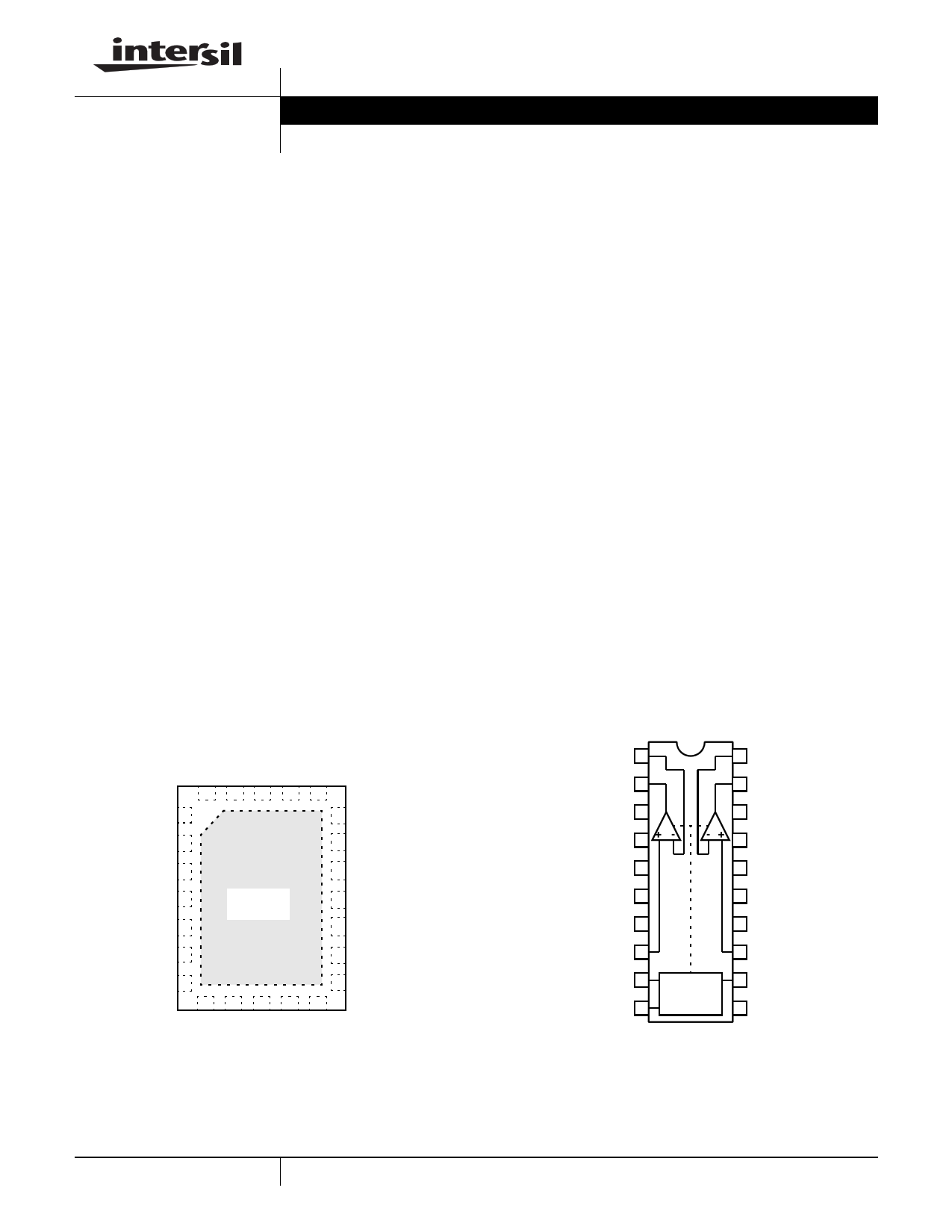
Pinouts
EL1503A
(24 LD QFN)
TOP VIEW
NC 1
NC 2
VS- 3
NC 4
NC 5
NC 6
GND 7
THERMAL
PAD
19 NC
18 NC
17 VS+
16 NC
15 NC
14 NC
13 GND
Features
• High power ADSL driver
• 39.2VP-P differential output drive into 22Ω
• 42.4VP-P differential output drive into 65Ω
• Driver 2nd/3rd harmonics of
-66dBc/-72dBc at 2VP-P into 100Ω differential
• Supply current of 12.5mA per amplifier
• Supply current control
• Power saving modes
• Standard surface-mount packages
• Ultra-small QFN package
• Pb-free plus anneal available (RoHS compliant)
Applications
• ADSL line drivers
• HDSL2 line drivers
• Video distribution amplifiers
EL1503A
[20 LD SOIC (0.300”)]
TOP VIEW
VIN-A 1
20 VIN-B
VOUTA 2
19 VOUTB
VS- 3
GND* 4
A
18 VS+
B
17 GND*
GND* 5
16 GND*
GND* 6
15 GND*
GND* 7
14 GND*
VIN+A 8
13 VIN+B
C1 9
C0 10
POWER
CONTROL
LOGIC
12 IADJ
11 NC
*GND pins are heat spreaders
1 CAUTION: These devices are sensitive to electrostatic discharge; follow proper IC Handling Procedures.
1-888-INTERSIL or 1-888-468-3774 | Intersil (and design) is a registered trademark of Intersil Americas Inc.
Copyright Intersil Americas Inc. 2002, 2003, 2005, 2007. All Rights Reserved
All other trademarks mentioned are the property of their respective owners.
1 page 
EL1503A
Typical Performance Curves (Continued)
25
RF=1.82kΩ
20
RF=2.0kΩ
VS=±12V
AV=10
RL=100Ω
RF=2.43kΩ
RF=2.74kΩ
25
VS=±5V
ARVL==11000Ω
RF=1.84kΩ
RF=2.0kΩ
20
RF=2.43kΩ
RF=2.74kΩ
15
100M
10M
1M
FREQUENCY (Hz)
100K
FIGURE 5. DRIVER DIFFERENTIAL FREQUENCY
RESPONSE vs RF (TERMINATE MODE)
19
VS=±12V
AV=5
RL=100Ω
14
RF=1.3kΩ
RF=1.5kΩ
RF=1.82kΩ
RF=2.0kΩ
RF=2.4kΩ
RF=2.74kΩ
9
100K
1M 10M
FREQUENCY (Hz)
100M
FIGURE 7. DRIVER DIFFERENTIAL FREQUENCY
RESPONSE vs RF (FULL POWER MODE)
19
VS=±12V
AV=5
RL=100Ω
14
RF=1.3kΩ
RF=1.5kΩ
RF=1.82kΩ
RF=2.0kΩ
RF=2.43kΩ
RF=2.74kΩ
9
100K
1M 10M
FREQUENCY (Hz)
100M
FIGURE 9. DRIVER DIFFERENTIAL FREQUENCY
RESPONSE vs RF (2/3 POWER MODE)
15
100K
1M 10M
FREQUENCY (Hz)
100M
FIGURE 6. DRIVER DIFFERENTIAL FREQUENCY
RESPONSE vs RF (TERMINATE MODE)
19
VS=±5V
AV=5
RL=100Ω
RF=1.5kΩ
RF=1.82kΩ
14
RF=2.0kΩ
RF=2.4k
RF=2.74k
9
100K
1M 10M
FREQUENCY (Hz)
100M
FIGURE 8. DRIVER DIFFERENTIAL FREQUENCY
RESPONSE vs RF (FULL POWER MODE)
19
VS=±5V
AV=5
RL=100Ω
14
RF=1.5kΩ
RF=1.82kΩ
RF=2.0kΩ
RF=2.4kΩ
RF=2.74kΩ
9
100K
1M 10M
FREQUENCY (Hz)
100M
FIGURE 10. DRIVER DIFFERENTIAL FREQUENCY
RESPONSE vs RF (2/3 POWER MODE)
5 FN7039.2
March 26, 2007
5 Page 
Test Circuit
EL1503A
1 VIN-A
2 VOUTA
3 VS-
4 GND
5 GND
6 GND
7 GND
8 VIN+A
9 C1
10 C0
VIN-B 20
VOUTB 19
VS+ 18
GND 17
GND 16
GND 15
GND 14
VIN+B 13
IADJ 12
NC 11
LEFT
DRIVER
OUT
R3
56Ω
1/2W
R7
1.5kΩ
0.1µF
TANTALUM
GND
5µF
C2
LEFT
DRIVER
IN
R2
51Ω
C1 C0
RS
100
1W
332Ω
1 20
2
3A
4
19
B
-+
18
17
5 16
6 15
7 14
8 13
9 12
10 11
R4
56Ω
1/2W
R16
1.5kΩ
RIGHT
DRIVER
OUT
5µF 0.1µF
VS+
TANTALUM
C1 GND
RSET
R17
51Ω
RIGHT
DRIVER
IN
11 FN7039.2
March 26, 2007
11 Page | ||
| Páginas | Total 17 Páginas | |
| PDF Descargar | [ Datasheet EL1503A.PDF ] | |
Hoja de datos destacado
| Número de pieza | Descripción | Fabricantes |
| EL1503A | High Power Differential Line Driver | Intersil Corporation |
| EL1503C | High Power Differential Line Driver | Elantec |
| EL1503CL | High Power Differential Line Driver | Elantec |
| EL1503CL-T13 | High Power Differential Line Driver | Elantec |
| Número de pieza | Descripción | Fabricantes |
| SLA6805M | High Voltage 3 phase Motor Driver IC. |
Sanken |
| SDC1742 | 12- and 14-Bit Hybrid Synchro / Resolver-to-Digital Converters. |
Analog Devices |
|
DataSheet.es es una pagina web que funciona como un repositorio de manuales o hoja de datos de muchos de los productos más populares, |
| DataSheet.es | 2020 | Privacy Policy | Contacto | Buscar |