|
|
|
PDF NUD4011 Data sheet ( Hoja de datos )
| Número de pieza | NUD4011 | |
| Descripción | Low Current LED Driver | |
| Fabricantes | ON Semiconductor | |
| Logotipo | ||
Hay una vista previa y un enlace de descarga de NUD4011 (archivo pdf) en la parte inferior de esta página. Total 9 Páginas | ||
|
No Preview Available !
www.DataSheet4U.com
NUD4011
Low Current LED Driver
This device is designed to replace discrete solutions for driving
LEDs in AC/DC high voltage applications (up to 200 V). An external
resistor allows the circuit designer to set the drive current for different
LED arrays. This discrete integration technology eliminates individual
components by combining them into a single package, which results in
a significant reduction of both system cost and board space. The
device is a small surface mount package (SO−8).
Features
• Supplies Constant LED Current for Varying Input Voltages
• External Resistor Allows Designer to Set Current – up to 70 mA
• Offered in Surface Mount Package Technology (SO−8)
• Pb−Free Package is Available
Benefits
• Maintains a Constant Light Output During Battery Drain
• One Device can be used for Many Different LED Products
• Reduces Board Space and Component Count
• Simplifies Circuit and System Designs
Typical Applications
• Portables: For Battery Back−up Applications, also Simple Ni−CAD
Battery Charging
• Industrial: General Lighting Applications and Small Appliances
• Automotive: Tail Lights, Directional Lights, Back−up Light,
Dome Light
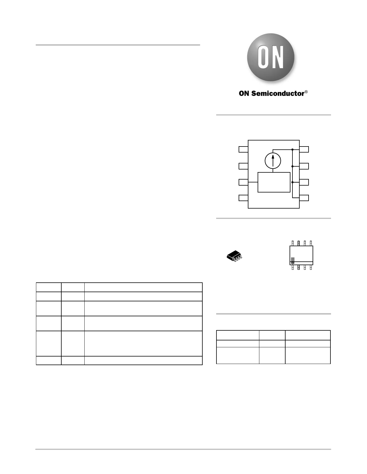
PIN FUNCTION DESCRIPTION
Pin Symbol
Description
1 Vin Positive input voltage to the device
2 Boost This pin may be used to drive an external transistor
as described in the App Note AND8198/D.
3 Rext An external resistor between Rext and Vin pins sets
different current levels for different application needs
4 PWM For high voltage applications (higher than 48 V),
pin 4 is connected to the LEDs array.
For low voltage applications (lower than 48 V), pin 4
is connected to ground.
5, 6, 7, 8 Iout The LEDs are connected from these pins to ground
http://onsemi.com
PIN CONFIGURATION
AND SCHEMATIC
Vin 1
Boost 2
Rext 3
PWM 4
Current
Set Point
8 Iout
7 Iout
6 Iout
5 Iout
8
1
SO−8
CASE 751
MARKING
DIAGRAM
8
4011
AYWWG
G
1
A = Assembly Location
Y = Year
WW = Work Week
G = Pb−Free Package
(Note: Microdot may be in either location)
ORDERING INFORMATION
Device
NUD4011DR2
NUD4011DR2G
Package
Shipping†
SO−8 2500 / Tape & Reel
SO−8 2500 / Tape & Reel
(Pb−Free)
†For information on tape and reel specifications,
including part orientation and tape sizes, please
refer to our Tape and Reel Packaging Specification
Brochure, BRD8011/D.
© Semiconductor Components Industries, LLC, 2006
June, 2006 − Rev. 3
1
Publication Order Number:
NUD4011/D
1 page 
NUD4011
APPLICATION INFORMATION (continued)
Design Guide for AC Applications
1. Define LED’s current:
a. ILED = 30 mA
2. Define Vin:
a. Per example in Figure 5, Vin = 120 Vac
3. Define VLED @ ILED per LED supplier’s data
sheet:
a. Per example in Figure 6,
VLED = 3.0 V (30 LEDs in series)
VLEDs = 90 V
4. Calculate Resistor Value for Rext:
The calculation of the Rext for AC applications is
totally different than for DC. This is because
current conduction only occurs during the time
that the ac cycles’ amplitude is higher than VLEDs.
Therefore Rext calculation is now dependent on the
peak current value and the conduction time.
a. Calculate q for VLEDs = 90 V:
V = Vpeak Sin q
90 V = (120 Ǹ2) Sin q
q = 32.027°
b. Calculate conduction time for q = 32.027°. For
a sinuousoidal waveform Vpeak happens at
q = 90°. This translates to 4.165 ms in time for
a 60 Hz frequency, therefore 32.027° is 1.48 ms
and finally:
Conduction time = (4.165 ms – 1.48 ms) 2
= 5.37 ms
c. Calculate the Ipeak needed for I(avg) = 30 mA
Since a full bridge rectifier is being used (per
Figure 6), the frequency of the voltage signal
applied to the NUD4011 device is now 120 Hz.
To simplify the calculation, it is assumed that
the 120 Hz waveform is square shaped so that
the following formula can be used:
I(avg) = Ipeak duty cycle;
If 8.33 ms is 100% duty cycle, then 5.37 ms is
64.46%, then:
Ipeak = I(avg) / duty cycle
Ipeak = 30 mA / 0.645 = 46 mA
d. Calculate Rext
Rext = 0.7 V / Ipeak
Rext = 15.21 W
5. Calculate Vdrop across the NUD4011 device:
a. Vdrop = Vin – Vsense – VLEDs
b. Vdrop = 120 V – 0.7 V – 90 V
c. Vdrop = 29.3 V
Full
Bridge
Rectifier 1
Vin
1
Boost
2 32
+
−
120 Vac
60 Hz
4
Rext
3
PWM
4
NUD4011
Current
Set Point
Iout
8
Iout
7
Iout
6
Iout
5
LED1
LED2
LED30
Figure 6. 120 Vac Application
(Series LED’s array)
6. Calculate Power Dissipation on the NUD4011
device’s driver:
a. PD_driver = Vdrop * I(avg)
b. PD_driver = 29.3 V 0.030 A
c. PD_driver = 0.879 W
7. Establish Power Dissipation on the
NUD4011device’s control circuit per below
formula:
a. PD_control = (Vin – 1.4 – VLEDs)@ / 20,000
b. PD_control = 0.040 W
8. Calculate Total Power Dissipation on the device:
a. PD_total = PD_driver + PD_control
b. PD_total = 0.879 W + 0.040 W = 0.919 W
9. If PD_total > 1.13 W (or derated value per
Figure 3), then select the most appropriate
recourse and repeat steps 1−8:
a. Reduce Vin
b. Reconfigure LED array to reduce Vdrop
c. Reduce Iout by increasing Rext
d. Use external resistors or parallel device’s
configuration
10. Calculate the junction temperature using the
thermal information on Page 8 and refer to
Figure 4 to check the output current drop due to
the calculated junction temperature. If desired,
compensate it by adjusting the value of Rext.
http://onsemi.com
5
5 Page | ||
| Páginas | Total 9 Páginas | |
| PDF Descargar | [ Datasheet NUD4011.PDF ] | |
Hoja de datos destacado
| Número de pieza | Descripción | Fabricantes |
| NUD4011 | Low Current LED Driver | ON Semiconductor |
| Número de pieza | Descripción | Fabricantes |
| SLA6805M | High Voltage 3 phase Motor Driver IC. |
Sanken |
| SDC1742 | 12- and 14-Bit Hybrid Synchro / Resolver-to-Digital Converters. |
Analog Devices |
|
DataSheet.es es una pagina web que funciona como un repositorio de manuales o hoja de datos de muchos de los productos más populares, |
| DataSheet.es | 2020 | Privacy Policy | Contacto | Buscar |