|
|
|
PDF TMP275 Data sheet ( Hoja de datos )
| Número de pieza | TMP275 | |
| Descripción | Digital Out Temperature Sensor | |
| Fabricantes | Burr-Brown | |
| Logotipo | ||
Hay una vista previa y un enlace de descarga de TMP275 (archivo pdf) en la parte inferior de esta página. Total 14 Páginas | ||
|
No Preview Available !
www.DataSheet4U.com
TMP275
SBOS363A − JUNE 2006 − REVISED JUNE 2006
0.5°C Digital Out Temperature Sensor
FEATURES
D 8 ADDRESSES
D DIGITAL OUTPUT: Two-Wire Serial Interface
D RESOLUTION: 9- to 12-Bits, User-Selectable
D ACCURACY:
±0.5°C (max) from +10°C to +85°C
±0.75°C (max) from +0°C to +100°C
D LOW QUIESCENT CURRENT:
50µA, 0.1µA Standby
D WIDE SUPPLY RANGE: 2.7V to 5.5V
D SMALL MSOP-8 PACKAGE
DESCRIPTION
The TMP275 is a 0.5°C accurate, two-wire, serial output
temperature sensor available in the MSOP-8 package. The
TMP275 is capable of reading temperatures with a resolution
of 0.0625°C.
The TMP275 is SMBus-compatible and allows up to eight
devices on one bus. It is ideal for extended temperature
measurement in a variety of communication, computer,
consumer, environmental, industrial, and instrumentation
applications.
The TMP275 is specified for operation over a temperature
range of −40°C to +125°C.
APPLICATIONS
D POWER-SUPPLY TEMPERATURE
MONITORING
D COMPUTER PERIPHERAL THERMAL
PROTECTION
D NOTEBOOK COMPUTERS
D CELL PHONES
D BATTERY MANAGEMENT
D OFFICE MACHINES
D THERMOSTAT CONTROLS
D ENVIRONMENTAL MONITORING AND HVAC
D ELECTROMECHANICAL DEVICE
TEMPERATURE
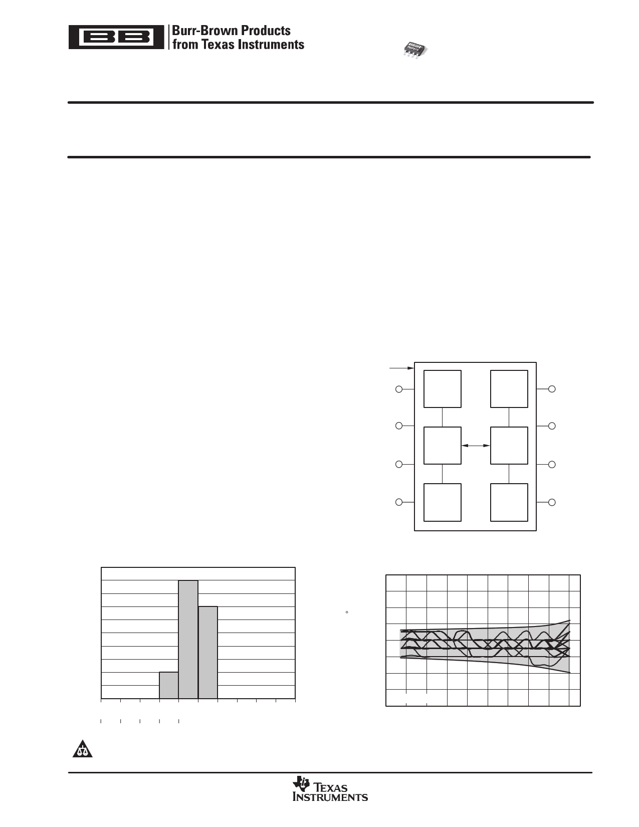
Temperature
SDA
1
Diode
Temp.
Sensor
SCL
ALERT
2
∆Σ
A/D
3 Converter
Control
Logic
8 V+
7
A0
Serial
Interface
6
A1
GND
4
OSC
Config.
and Temp.
Register
5
A2
TMP275
TEMPERATURE ERROR AT 25_C
0.500
0.375
0.250
0.125
0
−0.125
TEMPERATURE ERROR vs TEMPERATURE
−0.250
−0.375
36 Units Shown
−0.500
−55 −35 −15 5
25 45 65 85 105 125 130
Temperature Error (_C)
Temperature (_ C)
Please be aware that an important notice concerning availability, standard warranty, and use in critical applications of Texas Instruments
semiconductor products and disclaimers thereto appears at the end of this data sheet.
All trademarks are the property of their respective owners.
PRODUCTION DATA information is current as of publication date. Products
conform to specifications per the terms of Texas Instruments standard warranty.
Production processing does not necessarily include testing of all parameters.
Copyright 2006, Texas Instruments Incorporated
www.ti.com
1 page 
www.DataSheet4U.com
TMP275
www.ti.com
APPLICATIONS INFORMATION
The TMP275 is a digital temperature sensor that is optimal
for thermal management and thermal protection
applications. The TMP275 is Two-Wire and SMBus
interface-compatible, and is specified over a temperature
range of −40°C to +125°C.
The TMP275 requires no external components for
operation except for pull-up resistors on SCL, SDA, and
ALERT, although a 0.1µF bypass capacitor is
recommended, as shown in Figure 1.
V+
To
Two−Wire
Controller
SCL
SDA
8
7
2
6
1 TMP275 5
3
4
0.1µF
A0
A1
A2
ALERT
(Output)
NOTE: SCL, SDA, and ALERT
pins require pull−up resistors.
GND
Figure 1. Typical Connections of the TMP275
The sensing device of the TMP275 is the chip itself.
Thermal paths run through the package leads as well as
the plastic package. The lower thermal resistance of metal
causes the leads to provide the primary thermal path.
To maintain accuracy in applications requiring air or
surface temperature measurement, care should be taken
to isolate the package and leads from ambient air
temperature. A thermally-conductive adhesive will assist
in achieving accurate surface temperature measurement.
POINTER REGISTER
Figure 2 shows the internal register structure of the
TMP275. The 8-bit Pointer Register of the devices is used
to address a given data register. The Pointer Register uses
the two LSBs to identify which of the data registers should
respond to a read or write command. Table 1 identifies the
bits of the Pointer Register byte. Table 2 describes the
pointer address of the registers available in the TMP275.
Power-up reset value of P1/P0 is 00.
P7 P6 P5 P4 P3 P2 P1 P0
0 0 0 0 0 0 Register Bits
Table 1. Pointer Register Byte
SBOS363A − JUNE 2006 − REVISED JUNE 2006
Pointer
Register
Temperature
Register
Configuration
Register
TLOW
Register
I/O
Control
Interface
SCL
SDA
THIGH
Register
Figure 2. Internal Register Structure of the
TMP275
P1 P0 REGISTER
0 0 Temperature Register (READ Only)
0 1 Configuration Register (READ/WRITE)
1 0 TLOW Register (READ/WRITE)
1 1 THIGH Register (READ/WRITE)
Table 2. Pointer Addresses of the TMP275
TEMPERATURE REGISTER
The Temperature Register of the TMP275 is a 12-bit,
read-only register that stores the output of the most recent
conversion. Two bytes must be read to obtain data, and are
described in Table 3 and Table 4. Note that byte 1 is the
most significant byte, followed by byte 2, the least
significant byte. The first 12 bits are used to indicate
temperature, with all remaining bits equal to zero. The
least significant byte does not have to be read if that
information is not needed. Data format for temperature is
summarized in Table 5. Following power-up or reset, the
Temperature Register will read 0°C until the first
conversion is complete.
D7 D6 D5 D4 D3 D2 D1 D0
T11 T10 T9 T8 T7 T6 T5 T4
Table 3. Byte 1 of Temperature Register
D7 D6 D5 D4 D3 D2 D1 D0
T3 T2 T1 T0
0
0
0
0
Table 4. Byte 2 of Temperature Register
5
5 Page 
www.DataSheet4U.com
www.ti.com
SCL
1
91
TMP275
SBOS363A − JUNE 2006 − REVISED JUNE 2006
9
…
SDA
1 0 0 1 0 0 0 R/W
0 0 0 0 0 0 P1 P0
…
Start By
Master
Frame 1 Two−Wire Slave Address Byte
ACK By
TMP275
ACK By
TMP275
Frame 2 Pointer Register Byte
SCL
(Continued)
1
91
9
…
SDA
(Continued)
Start By
Master
1
0 0 1 0 0 0 R/W
D7 D6 D5 D4 D3 D2 D1 D0
Frame 3 Two−Wire Slave Address Byte
ACK By
TMP275
From
TMP275
Frame 4 Data Byte 1 Read Register
…
ACK By
Master
SCL
(Continued)
1
9
SDA
(Continued) D7 D6
D5 D4 D3 D2 D1 D0
From
TMP275
ACK By
Master
Frame 5 Data Byte 2 Read Register
Stop By
Master
NOTE: Address Pins A0, A1, A2 = 0
Figure 6. Two-Wire Timing Diagram for Read Word Format
ALERT
SCL
1
91
9
SDA
0 0 0 1 1 0 0 R/W
1 0 0 1 0 0 0 S tatu s
Start By
Master
ACK By
TMP275
Frame 1 SMBus ALERT Response Address Byte
From
TMP275
Frame 2 Slave Address Byte
NACK By Stop By
Master Master
NOTE: Address Pins A0, A1, A2 = 0
Figure 7. Timing Diagram for SMBus ALERT
11
11 Page | ||
| Páginas | Total 14 Páginas | |
| PDF Descargar | [ Datasheet TMP275.PDF ] | |
Hoja de datos destacado
| Número de pieza | Descripción | Fabricantes |
| TMP275 | Temperature Sensor (Rev. E) | Texas Instruments |
| TMP275 | Digital Out Temperature Sensor | Burr-Brown |
| TMP275-Q1 | Temperature Sensor (Rev. A) | Texas Instruments |
| Número de pieza | Descripción | Fabricantes |
| SLA6805M | High Voltage 3 phase Motor Driver IC. |
Sanken |
| SDC1742 | 12- and 14-Bit Hybrid Synchro / Resolver-to-Digital Converters. |
Analog Devices |
|
DataSheet.es es una pagina web que funciona como un repositorio de manuales o hoja de datos de muchos de los productos más populares, |
| DataSheet.es | 2020 | Privacy Policy | Contacto | Buscar |