|
|
|
PDF AD7142 Data sheet ( Hoja de datos )
| Número de pieza | AD7142 | |
| Descripción | Programmable Controller | |
| Fabricantes | Analog Devices | |
| Logotipo | ||
Hay una vista previa y un enlace de descarga de AD7142 (archivo pdf) en la parte inferior de esta página. Total 30 Páginas | ||
|
No Preview Available !
FEATURES
Programmable capacitance-to-digital converter
36 ms update rate (@ maximum sequence length)
Better than 1 fF resolution
14 capacitance sensor input channels
No external RC tuning components required
Automatic conversion sequencer
On-chip automatic calibration logic
Automatic compensation for environmental changes
Automatic adaptive threshold and sensitivity levels
On-chip RAM to store calibration data
SPI®-compatible serial interface (AD7142)
I2C®-compatible serial interface (AD7142-1)
Separate VDRIVE level for serial interface
Interrupt output and GPIO
32-lead, 5 mm x 5 mm LFCSP_VQ
2.6 V to 3.6 V supply voltage
Low operating current
Full power mode: less than 1 mA
Low power mode: 50 μA
APPLICATIONS
Personal music and multimedia players
Cell phones
Digital still cameras
Smart hand-held devices
Television, A/V, and remote controls
Gaming consoles
GENERAL DESCRIPTION
The AD7142 and AD7142-1 are integrated capacitance-to-
digital converters (CDCs) with on-chip environmental
calibration for use in systems requiring a novel user input
method. The AD7142 and AD7142-1 can interface to external
capacitance sensors implementing functions such as capacitive
buttons, scroll bars, or wheels.
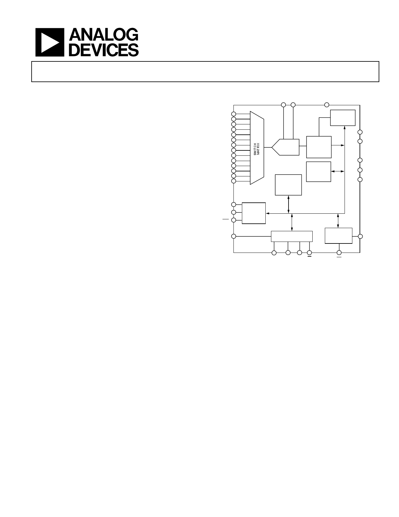
The CDC has 14 inputs channeled through a switch matrix to a
16-bit, 250 kHz sigma-delta (∑-Δ) capacitance-to-digital
converter. The CDC is capable of sensing changes in the
capacitance of the external sensors and uses this information to
register a sensor activation. The external sensors can be
arranged as a series of buttons, as a scroll bar or wheel, or as a
combination of sensor types. By programming the registers, the
user has full control over the CDC setup. High resolution
sensors require minor software to run on the host processor.
Rev. A
Information furnished by Analog Devices is believed to be accurate and reliable. However, no
responsibility is assumed by Analog Devices for its use, nor for any infringements of patents or other
rights of third parties that may result from its use. Specifications subject to change without notice. No
license is granted by implication or otherwise under any patent or patent rights of Analog Devices.
Trademarksandregisteredtrademarksarethepropertyoftheirrespectiveowners.
Programmable Controller for
Capacitance Touch Sensors
AD7142
CIN0
CIN1
CIN2
CIN3
CIN4
CIN5
CIN6
CIN7
CIN8
CIN9
CIN10
CIN11
CIN12
CIN13
30
31
32
1
2
3
4
5
6
7
8
9
10
11
FUNCTIONAL BLOCK DIAGRAM
VREF– VREF+
29 28
TEST
27
POWER-ON
RESET
LOGIC
16-BIT
Σ-Δ
CDC
CALIBRATION
ENGINE
CONTROL
AND
DATA
REGISTERS
CALIBRATION
RAM
13 AVCC
14 AGND
17 DVCC
18 DGND1
19 DGND2
CSHIELD 12
SRC 15
SRC 16
250kHz
EXCITATION
SOURCE
VDRIVE 20
SERIAL INTERFACE
AND CONTROL LOGIC
INTERRUPT
AND GPIO
LOGIC
26 GPIO
21
SDO/
SDA
22 23 24
SDI/
ADD0
SCLK
CS/
ADD1
Figure 1.
25
INT
The AD7142 and AD7142-1 have on-chip calibration logic to
account for changes in the ambient environment. The calibration
sequence is performed automatically and at continuous intervals,
when the sensors are not touched. This ensures that there are no
false or nonregistering touches on the external sensors due to a
changing environment.
The AD7142 has an SPI-compatible serial interface, and the
AD7142-1 has an I2C-compatible serial interface. Both parts
have an interrupt output, as well as a general-purpose input/
output (GPIO).
The AD7142 and AD7142-1 are available in a 32-lead, 5 mm ×
5 mm LFCSP_VQ and operate from a 2.6 V to 3.6 V supply. The
operating current consumption is less than 1 mA, falling to
50 μA in low power mode (conversion interval of 400 ms).
One Technology Way, P.O. Box 9106, Norwood, MA 02062-9106, U.S.A.
Tel: 781.329.4700
www.analog.com
Fax: 781.461.3113
©2007 Analog Devices, Inc. All rights reserved.
1 page 
AD7142
PLASTIC OVERLAY
SENSOR BOARD
CAPACITIVE SENSOR
CIN
CBULK
Figure 2.
Table 2. Typical Average Current in Low Power Mode, AVCC, DVCC = 3.6 V, T= 25°C, Load of 50 pF on SRC Pin, No Load on SRC
Number of Conversion Stages (Current Values Expressed in μA)
Low Power Mode Decimation
Delay
Rate
1 2 3 4 5 6 7 8 9 10 11
200 ms 128 26.4 33.3 40.1 46.9 53.5 60 66.5 72.8 79.1 85.2 91.3
256 35.6 49.1 62.2 74.9 87.3 99.3 111 122.3 133.4 144.2 154.7
400 ms 128 21.3 24.8 28.3 31.7 35.2 38.6 42 45.4 48.7 52 55.3
256 26 32.9 39.7 46.5 53.1 59.6 66.1 72.4 78.7 84.9 91
600 ms 128 19.6 21.9 24.3 26.6 28.9 31.2 33.5 35.8 38.1 40.4 42.6
256 22.7 27.4 32 36.6 41.1 45.6 50 54.4 58.8 63.1 67.4
800 ms 128 18.7 20.5 22.2 24 25.7 27.5 29.2 31 32.7 34.4 36.1
256 21.1 24.6 28.1 31.5 35 38.4 41.8 45.2 48.5 51.8 55.1
12
97.3
164.9
58.6
97
44.8
71.6
37.8
58.4
Table 3. Maximum Average Current in Low Power Mode, AVCC, DVCC = 3.6 V, Load of 50 pF on SRC Pin, No Load on SRC
Number of Conversion Stages (Current Values Expressed in μA)
Low Power Mode Decimation
Delay
Rate
1 2 3 4 5 6 7 8 9 10 11
200 ms
128 45.4 53.6 61.5 69.4 77.1 84.7 92.2 99.6 106.8 113.9 121
256
56.2 72
87.2 102 116.3 130.2 143.7 156.8 169.5 181.8 193.8
400 ms
128 39.5 43.6 47.7 51.8 55.8 59.8 63.7 67.6 71.5 75.4 79.2
256 45 53.1 61.1 68.9 76.7 84.3 91.8 99.1 106.4 113.6 120.6
600 ms
128
37.5 40.3 43
45.8 48.5 51.2 53.9 56.5 59.2 61.8 64.5
256 41.2 46.7 52.1 57.4 62.7 67.9 73.1 78.2 83.3 88.3 93.3
800 ms
128 36.5 38.6 40.7 42.7 44.8 46.8 48.8 50.9 52.9 54.9 56.9
256 39.3 43.4 47.5 51.5 55.6 59.5 63.5 67.4 71.3 75.2 79
12
127.9
205.5
83
127.5
67.1
98.2
58.9
82.8
Rev. A | Page 5 of 72
5 Page 
960
940
3.6V
920
900
3.3V
880
860
840
820
2.7V
800
780
–40
–20
0 20 40 60 80 100 120
TEMPERATURE (°C)
Figure 14. Supply Current vs. Temperature (Supply Current = AICC + DICC)
12
10
8
6
3.6V
3.3V
4
2
0
–40 –20
2.7V
0 20 40 60 80 100 120
TEMPERATURE (°C)
Figure 15. Shutdown Supply Current vs. Temperature
(Supply Current = AICC + DICC)
AD7142
2.5
100mV
300mV
200mV
400mV
500mV
2.0
1.5
1.0
0.5
0
10 1k 100k
FREQUENCY (Hz)
Figure 16. Power Supply Sine Wave Rejection
10M
180
160
140
120
100
300mV
80
60
40
20
0
100
200mV
100mV
50mV
25mV
1k 10k 100k 1M
SQUARE WAVE FREQUENCY (Hz)
10M
Figure 17. Power Supply Square Wave Rejection
Rev. A | Page 11 of 72
11 Page | ||
| Páginas | Total 30 Páginas | |
| PDF Descargar | [ Datasheet AD7142.PDF ] | |
Hoja de datos destacado
| Número de pieza | Descripción | Fabricantes |
| AD7142 | Programmable Controller | Analog Devices |
| AD7143 | integrated capacitance-to-digital converter | Analog Devices |
| AD7147 | CapTouch Programmable Controller | Analog Devices |
| AD7147A | CapTouch Programmable Controller | Analog Devices |
| Número de pieza | Descripción | Fabricantes |
| SLA6805M | High Voltage 3 phase Motor Driver IC. |
Sanken |
| SDC1742 | 12- and 14-Bit Hybrid Synchro / Resolver-to-Digital Converters. |
Analog Devices |
|
DataSheet.es es una pagina web que funciona como un repositorio de manuales o hoja de datos de muchos de los productos más populares, |
| DataSheet.es | 2020 | Privacy Policy | Contacto | Buscar |