|
|
|
PDF MC34118 Data sheet ( Hoja de datos )
| Número de pieza | MC34118 | |
| Descripción | Voice Switched Speaker Phone Circuit | |
| Fabricantes | Unisonic Technologies | |
| Logotipo | ||
Hay una vista previa y un enlace de descarga de MC34118 (archivo pdf) en la parte inferior de esta página. Total 15 Páginas | ||
|
No Preview Available !
UNISONIC TECHNOLOGIES CO., LTD
MC34118
LINEAR INTEGRATED CIRCUIT
VOICE SWITCHED
SPEAKER-PHONE CIRCUIT
DESCRIPTION
As a voice switched speaker-phone integrated circuit, the UTC
MC34118 includes the necessary amplifiers, attenuators, level
detectors and control algorithm.
To form the UTC MC34118’s internal circuit, there is an internal
microphone amplifier with adjustable gain and mute control, internal
transmit and Receive attenuators (operate in a complementary
manner), level detectors at both input and output of both attenuators,
and background noise monitors for both the transmit and receive
channels.
The dial tone can be pretended from being attenuated by the
receive background noise monitor circuit by a dial tone detector.
There are also two line driver amplifiers which can be used to form a
hybrid network in conjunction with an external coupling transformer. A
high-pass filter can be used for other filtering functions, and especially
to filter out 60Hz noise in the receive channel.
The UTC MC34118 which requiring typically 5mA may be
operated from a power supply, or it can be powered from the
telephone line.
FEATURES
* Attenuator gain range: 52dB (between Transmit and Receive)
* For line-powered applications : 3~6.5V low voltage operation
* For improved sensitivity :4-point signal sensing
* For Transmit and Receive paths: background noise monitors
* External resistors set microphone amplifier gain
* Mute function included
* Chip disable: active or standby operation
* During dial tone presence: dial tone detector to inhibit receive idle
mode
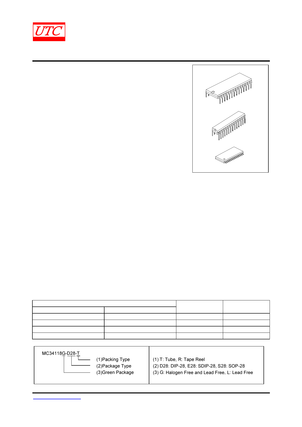
ORDERING INFORMATION
Ordering Number
Lead Free
Halogen Free
- MC34118G-D28-T
MC34118L-E28-T
MC34118G-E28-T
- MC34118G-S28-T
- MC34118G-S28-R
Package
DIP-28
SDIP-28
SOP-28
SOP-28
DIP-28
SDIP-28
SOP-28
Packing
Tube
Tube
Tube
Tape Reel
www.unisonic.com.tw
Copyright © 2014 Unisonic Technologies Co., Ltd
1 of 15
QW-R108-007.F
1 page 
UNISONIC TECHNOLOGIES CO., LTD
MC34118
LINEAR INTEGRATED CIRCUIT
ABSOLUTE MAXIMUM RATING (TA=25°С,Voltages referred to pin 22)
PARAMETER
SYMBOL
RATINGS
UNIT
Supply Voltage
VCC
-1~7
V
Voltage at Pin 3
V3
-1~VCC+1
V
Voltage at Pin 12 ( mute)
V12
-1~VCC +1
V
Voltage at Pin 13 ( VLC)
V13
-1~VCC+0.5
V
Voltage at Pin 9, Pin 21, and Pin 2
V9, 21, 2
-0.5~ VCC+0.5
V
Storage Temperature
TSTR
-65~+150
°С
Note: Absolute maximum ratings are those values beyond which the device could be permanently damaged.
Absolute maximum ratings are stress ratings only and functional device operation is not implied.
RECOMMENDED OPERATION CONDITIONS
PARAMETER
Supply Voltage
Voltage at Pin 3
Voltage at Pin 12 ( MUTE)
Voltage at Pin 13 ( VLC)
IVB Current ( Pin 15)
Attenuator Input Signal Voltage at Pin 9, Pin 21
RXO, TXO(Pin8, Pin 22)
Load Current
MCO(Pin 10)
HTO-, HTO+(Pin 6, Pin5)
Ambient Operating Temperature
SYMBOL
V4
V3
V12
V13
IVB
V9, V21
TOPR
RATINGS
3.5~6.5
0~ VCC
0~ VCC
0.3×VB~VB
500
350
0~+-2
0~+-1
0~+-0.5
-20~+60
ELECTRICAL CHARACTERISTICS (TA= 25°C, unless otherwise specified)
UNIT
V
V
V
V
µA
mVrms
mA
mA
mA
°С
PARAMETER
SYMBOL
TEST CONDITIONS
Supply Voltages
V+ Supply Current
CD Input Resistance
CD Input Voltage
High
Low
VB Output Voltage
VB Output Resistance
VB Power Supply Rejection Ratio
ICC
RCD
VCDH
VCDL
VB
ROVB
PSRR
VCC=6.5V, CD=0.8V
VCC =6.5V, CD=2V
VCC =VCD=6.5V
VCC =3.5V
VCC =5V
IVB=1mA
CVB=220µF, f=1kHz
Attenuators
RX Mode, RXI=150mVrms
Receive Attenuator
Gain
(f=1kHz, VLC=VB)
RX Mode, RXI=150mVrms
Gain Change
AGC Gain Change
Idle Mode, RXI=150mVrms
RX to TX Mode Range
Volume Control Range
RXO DC Voltage
RXO DC Voltage
RXO High Voltage
RXO Low Voltage
RXI Input Resistance
GRX
GRX
GRX1
GRX2
GRXI
GRX3
VCR
VRXO
VRXO
VRXOH
VRXOL
RRXI
VCC=5V
VCC =3.5V
VCC =3.5V vs. VCC =5V
VCC =3.5V vs. VCC =5V
RX Mode
RX to TX Mode
IOUT=-1mA, RXI=VB+1.5V
IOUT=+1mA, RXI=VB-1V,
Output Measured with
Respect to VB
RXI<350mVrs
MIN TYP MAX UNIT
5.5 8 mA
600 800 μA
50 90
kΩ
2 VCC V
0.8 V
1.3 V
1.8 2.1 2.4
400 Ω
54 dB
4 6 8 dB
4 6 8 dB
-0.5 0 +0.5 dB
-25 -15 dB
-22 -20 -17 dB
49 52 54 dB
27 35
dB
VB V
+-10 +-150 mV
3.7 V
-1.5 -1 V
7 10 14 kΩ
UNISONIC TECHNOLOGIES CO., LTD
www.unisonic.com.tw
5 of 15
QW-R108-007.F
5 Page 
UNISONIC TECHNOLOGIES CO., LTD
MC34118
LINEAR INTEGRATED CIRCUIT
FUNCTIONAL DESCRIPTION(Cont.)
AGC
The AGC circuit only affects the circuit under such situation: when the circuit is in the receive mode, and when
VCC is less than 3.5v. As while as VCC falls below 3.5 volts, the transmit path attenuation changes so that the sum of
the transmit and receive gains remains constant.
ATTENUATOR CONTROL BLOCK
This block has the seven:
* C1: The output of the comparator operated by RLO2 and TLO2 (here means in microphone/ speaker side).
* C2: The output of the comparator operated by RLO1 and TLO1 (here means Tip/ Ring side).
* C3: The output of the transmit background noise monitor.
* C4: The output of the receive background noise monitor.
* Volume control
* Dial tone detector
* AGC circuit
The C1~C4 effect is as follows:
INPUTS
C1 C2 C3 C4
TX TX
TX RX
1
Y
X
Y
RX TX
RX RX
Y
X
Y
1
TX TX
TX RX
0
0
X
0
RX TX
RX RX
0
X
0
0
Switching to the full transmit or receive from any other mode is at the fast rate (~30 ms).
X :Don’t care
Y :C3,C4 are not both 0
OUTPUT
Transmit Mode
Fast Idle Mode
Fast Idle Mode
Receive Mode
Slow Idle Mode
Slow Idle Mode
Slow Idle Mode
Slow Idle Mode
UNISONIC TECHNOLOGIES CO., LTD
www.unisonic.com.tw
11 of 15
QW-R108-007.F
11 Page | ||
| Páginas | Total 15 Páginas | |
| PDF Descargar | [ Datasheet MC34118.PDF ] | |
Hoja de datos destacado
| Número de pieza | Descripción | Fabricantes |
| MC3411 | P-Channel 20-V (D-S) MOSFET | Freescale |
| MC34114 | TELEPHONE SPEECH NETWORK WITH DIALER INTERFACE | Motorola Semiconductors |
| MC34115 | CONTINUOUSLY VARIABLE SLOPE DELTA MODULATOR/DEMODULATOR | Motorola Semiconductors |
| MC34117 | Telephone Tone Riger | Motorola Semiconductors |
| Número de pieza | Descripción | Fabricantes |
| SLA6805M | High Voltage 3 phase Motor Driver IC. |
Sanken |
| SDC1742 | 12- and 14-Bit Hybrid Synchro / Resolver-to-Digital Converters. |
Analog Devices |
|
DataSheet.es es una pagina web que funciona como un repositorio de manuales o hoja de datos de muchos de los productos más populares, |
| DataSheet.es | 2020 | Privacy Policy | Contacto | Buscar |