|
|
|
PDF LM5033SDX Data sheet ( Hoja de datos )
| Número de pieza | LM5033SDX | |
| Descripción | 100V Push-Pull Voltage Mode PWM Controller | |
| Fabricantes | National Semiconductor | |
| Logotipo | ||
Hay una vista previa y un enlace de descarga de LM5033SDX (archivo pdf) en la parte inferior de esta página. Total 16 Páginas | ||
|
No Preview Available !
April 2004
LM5033
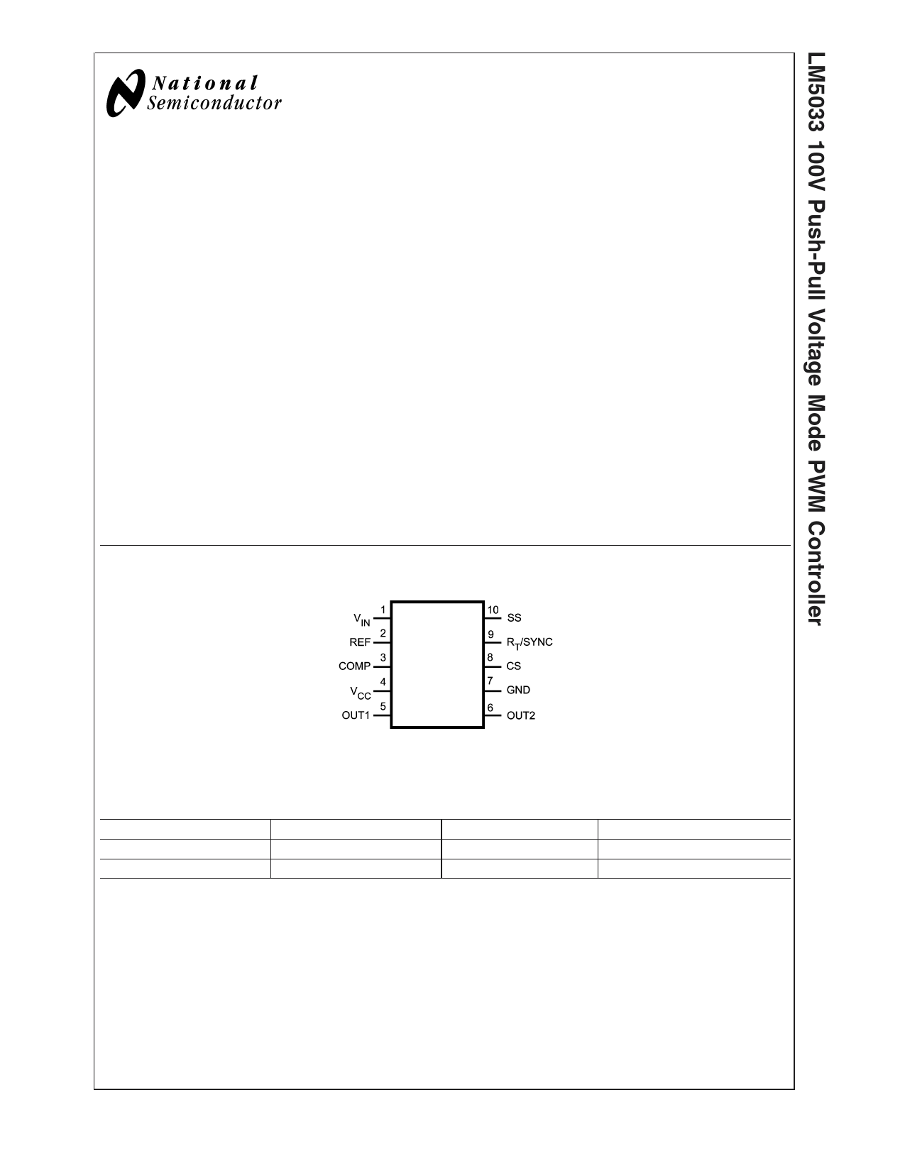
100V Push-Pull Voltage Mode PWM Controller
General Description
The LM5033 High Voltage PWM controller contains all the
features needed to implement Push-Pull, Half-Bridge, and
Full-Bridge topologies. Applications include closed loop volt-
age mode converters with a highly regulated output voltage,
or an open loop "DC transformer" such as an Intermediate
Bus Converter (IBC) with an efficiency >95%. The small 10
pin LLP-10 package with exposed pad provides for efficient
thermal management. Two alternating gate driver outputs
with a guaranteed deadtime are provided. The LM5033 in-
cludes a start-up regulator that operates over a wide input
range of 15V to 100V. Additional features include: precision
voltage reference output, current limit detection, remote
shutdown, softstart, sync capability and thermal shutdown.
This high speed IC has total propagation delays less than
100 ns and a 1MHz capable oscillator.
Features
n Internal high voltage (100V) start-up regulator
n Single resistor oscillator setting
n Synchronizable
n Precision reference output
n Adjustable soft-start
n Over-current protection
n Direct optocoupler interface
n 1.5A peak gate drivers
n Thermal Shutdown
Applications
n Intermediate DC/DC Bus Converter
n Telecommunication Power Converters
n Industrial Power Converters
n +42V Automotive Systems
Package
n LLP-10
Connection Diagram
20035401
10 -Lead Plastic, Dual, LLP
Ordering Information
Order Number
LM5033SD
LM5033SDX
Package Type
LLP-10 (4 x 4 mm)
LLP-10 (4 x 4 mm)
NSC Package Drawing
SDC10A
SDC10A
Supplied As
1000 Units on Tape and Reel
4500 Units on Tape and Reel
© 2004 National Semiconductor Corporation DS200354
www.national.com
1 page 
Electrical Characteristics (Continued)
Specifications with standard typeface are for TJ = 25˚C, and those with boldface type apply over full Operating Junction
Temperature range. VIN = 48V, VCC = 10V applied externally, RT = 26.7kΩ, unless otherwise stated. See (Note 4) and (Note
5).
Symbol Parameter
Conditions
Min
Typ
Max
Units
Oscillator (Pin 9)
Fs1
Internal frequency
Rt = 26.7 kΩ
175 200 225 kHz
Fs2
Internal frequency
Rt = 8.2 kΩ
600 kHz
Vsync
Sync threshold
3.2 3.8 V
Rt/Sync DC voltage
PWM Comparator Input (Pin 3)
2.0 V
tPWM
Gain from pin 3 to
PWM comparator
0.34
V/V
Maximum duty cycle at
Out1, Out2
Minimum duty cycle at
Out1, Out2
See PWM Comparator
text
Pin 3 = 0V.
100 x
(0.5TS-TD)/TS
0
%
%
Open Circuit Voltage
4.2 5.2 6.2 V
Short circuit current
Pin 3 = 0V
0.6 1.1 1.5 mA
Output Drivers (Pin 5, 6)
Deadtime (TD)
CLoad = 0 @ OUT1,
OUT2. Time measured
from 10% of falling
output to 10% of rising
output.
85
135 185 ns
Rise Time
Fall Time
Output High Voltage
CLoad = 1nF
CLoad = 1nF
Iout = 50 mA (source)
Vcc-0.75
16
16
Vcc-0.25
ns
ns
V
Output Low Voltage
Iout = 100 mA (sink)
0.25
0.75
V
Max. source current
1.5 A
Max. sink current
1.5 A
Thermal Shutdown
TSD Shutdown temperature
Shutdown temperature
hysteresis
165 ˚C
15 ˚C
Thermal Resistance
θJA
Junction to Ambient
SDC10A Package
38 ˚C/W
Note 1: Absolute Maximum Ratings are limits beyond which damage to the device may occur. Operating Ratings are conditions under which operation of the device
is intended to be functional. For guaranteed specifications and test conditions, see the Electrical Characteristics.
Note 2: The maximum allowable power dissipation is a function of the maximum allowed junction temperature (TJ(max)), the ambient temperature (TA), and the
junction-to-ambient thermal resistance (θJA). The maximum allowable power dissipation can be calculated from PD = (TJ(max) - TA) / θJA. Excessive power dissipation
will cause the thermal shutdown to activate.
Note 3: The human body model is a 100 pF capacitor discharged through a 1.5kΩ resistor into each pin.
Note 4: Min and Max limits are 100% production tested at 25˚C. Limits over the operating temperature range are guaranteed through correlation using Statistical
Quality Control (SQC) methods. Limits are used to calculate National’s Average Outgoing Quality Level (AOQL).
Note 5: Typical specifications represent the most likely parametric norm at 25˚C operation.
5 www.national.com
5 Page 
Application Information (Continued)
FIGURE 3. Deadtime Adjustment
20035416
PC BOARD LAYOUT
The LM5033 current sense and PWM comparators are very
fast, and as such will respond to short duration noise pulses.
Layout considerations are critical for the current sense filter.
The components at pins 3, 8, 9, and 10 should be as
physically close as possible to the IC, thereby minimizing
noise pickup in the PC tracks.
If a current sense transformer is used both leads of the
transformer secondary should be routed to the sense filter
components, and to the IC pins. The ground side of the
transformer should be connected via a dedicated PC board
track to pin 7 of the IC rather than through the ground plane.
If the current sense circuit employs a sense resistor in the
drive transistor sources, a low inductance resistor should be
used. In this case all the noise sensitive low power grounds
should be connected in common near the IC, and then a
single connection made to the power ground (sense resistor
ground point).
The outputs of the LM5033, or of the high voltage gate driver
(if used), should have short direct paths to the power MOS-
FETs in order to minimize the effects of inductance in the PC
board traces.
If the internal dissipation of the LM5033 and any of the power
devices produces high junction temperatures during normal
operation, good use of the PC board’s ground plane can help
considerably to dissipate heat. The exposed pad on the
bottom of the LLP-10 package can be soldered to ground
plane on the PC board, and the ground plane should extend
out from beneath the IC to help dissipate the heat. The
exposed pad is internally connected to the IC substrate.
Additionally, the use of wide PC board traces where possible
can help conduct heat away from the IC. Judicious position-
ing of the PC board within the end product, along with use of
any available air flow (forced or natural convection) can help
reduce the junction temperatures.
APPLICATION CIRCUIT EXAMPLE
Figure 6 shows an example circuit for a half-bridge 200W
DC/DC converter built in a quarter brick format. The circuit is
that of an intermediate bus converter (IBC) which operates
open-loop (unregulated output), converting a nominal 48V
input to a nominal 9.0V output with a 30 mΩ output imped-
ance. The current sense transformer (T2), and the associ-
ated filter at the CS pin, provide overcurrent detection at
approximately 23A. The auxiliary winding on T1 powers VCC
and the LM5100’s V+ pin (once the outputs are enabled) to
reduce power dissipation within the LM5033. The LM5100
provides appropriate level shifting for Q1. Synchronous rec-
tifiers Q3 and Q4 minimize conduction losses in the output
stage. Dual comparators U2 and U3 provide under-voltage
and over-voltage sensing at Vin. The under-voltage sense
levels are 37V increasing, and 33V decreasing. The over-
voltage sense levels are 63V increasing, and 61.5V decreas-
ing. The circuit can be shut down by taking the ON/OFF input
below 0.8V. An external synchronizing frequency can be
applied to the SYNC input. Measured efficiency and output
characteristics for this circuit are shown in Figure 4 and
Figure 5.
11 www.national.com
11 Page | ||
| Páginas | Total 16 Páginas | |
| PDF Descargar | [ Datasheet LM5033SDX.PDF ] | |
Hoja de datos destacado
| Número de pieza | Descripción | Fabricantes |
| LM5033SD | 100V Push-Pull Voltage Mode PWM Controller | National Semiconductor |
| LM5033SDX | 100V Push-Pull Voltage Mode PWM Controller | National Semiconductor |
| Número de pieza | Descripción | Fabricantes |
| SLA6805M | High Voltage 3 phase Motor Driver IC. |
Sanken |
| SDC1742 | 12- and 14-Bit Hybrid Synchro / Resolver-to-Digital Converters. |
Analog Devices |
|
DataSheet.es es una pagina web que funciona como un repositorio de manuales o hoja de datos de muchos de los productos más populares, |
| DataSheet.es | 2020 | Privacy Policy | Contacto | Buscar |