|
|
|
PDF LM5030 Data sheet ( Hoja de datos )
| Número de pieza | LM5030 | |
| Descripción | 100V Push-Pull Current Mode PWM Controller | |
| Fabricantes | National Semiconductor | |
| Logotipo | ||
Hay una vista previa y un enlace de descarga de LM5030 (archivo pdf) en la parte inferior de esta página. Total 11 Páginas | ||
|
No Preview Available !
August 2003
LM5030
100V Push-Pull Current Mode PWM Controller
General Description
The LM5030 High Voltage PWM controller contains all of the
features needed to implement Push-Pull and Bridge topolo-
gies, using current-mode control in a small 10 pin package.
This device provides two alternating gate driver outputs. The
LM5030 includes a high-voltage start-up regulator that oper-
ates over a wide input range of 14V to 100V. Additional
features include: error amplifier, precision reference, dual
mode current limit, slope compensation, softstart, sync ca-
pability and thermal shutdown. This high speed IC has total
propagation delays less than 100ns and a 1MHz capable
single resistor adjustable oscillator.
Package: MSOP-10 (Contact factory for thermally enhanced
LLP availability).
Features
n Internal High Voltage Start-up Regulator
n Single Resistor Oscillator Setting
n Synchronizable
n Error Amplifier
n Precision Reference
n Adjustable Softstart
n Dual Mode Over-Current Protection
n Slope Compensation
n Direct Optocoupler Interface
n 1.5A Peak Gate Drivers
n Thermal Shutdown
Applications
n Telecommunication Power Converters
n Industrial Power Converters
n +42V Automotive Systems
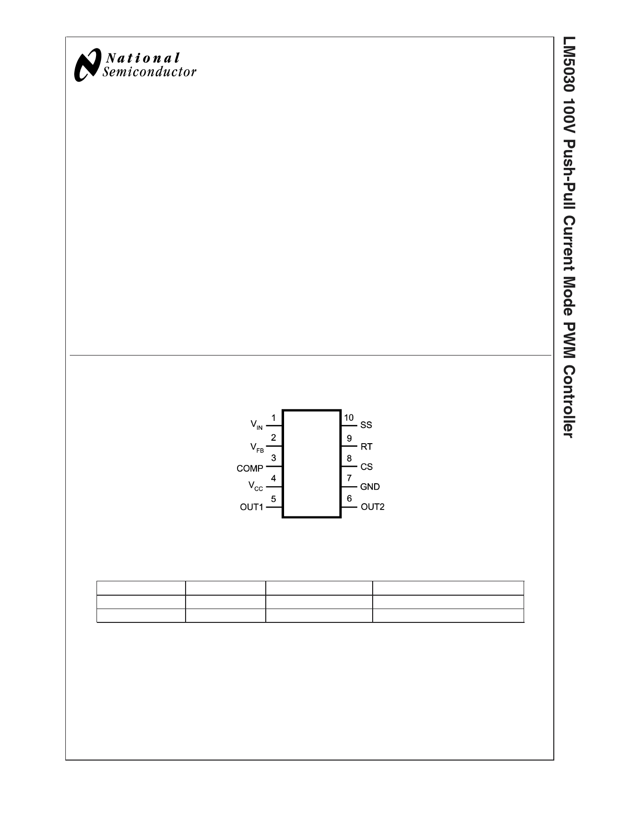
Connection Diagram
Top View
10-Lead MSOP
20058112
Ordering Information
Order Number
LM5030MM
LM5030MMX
Package Marking
S73B
S73B
NSC Package Drawing
MUB10A
MUB10A
Supplies As
1000 Units on Tape and Reel
3500 Units on Tape and Reel
© 2003 National Semiconductor Corporation DS200581
www.national.com
1 page 
Electrical Characteristics (Continued)
Specifications in standard type face are for TJ= +25˚C and those in boldface type apply over the full operating junction tem-
perature range. Unless otherwise specified: VIN = 48V, VCC = 10V, and RT = 26.7KΩ
Symbol
Parameter
Conditions
Min Typ
Max
Units
(Note 4) (Note 5)
(Note 4)
Oscillator
Frequency1 (RT = 26.7K)
175 200 225 kHz
Frequency2 (RT = 8.2K)
510 600 690 kHz
Sync threshold
3.2 3.8
V
PWM Comparator
Delay to Output
COMP set to 2V CS
30
ns
stepped 0 to 0.4V, Time
to onset of OUT transition
low
Max Duty Cycle
Inferred from deadtime
47.5
49
50
%
Min Duty Cycle
COMP=0V
0%
COMP to PWM Comparator
0.34
Gain
COMP Open Circuit Voltage
VFB = 0V
4.3 5.2
6.1
V
COMP Short Circuit Current
VFB = 0V, COMP=0V
0.6
1.1
1.5
mA
Slope Compensation
Slope Comp Amplitude
Delta increase at PWM
80
105
130
mV
Comparator to CS
Output Section
Deadtime
Cload = 0, 10% to 10%
85
135
185
ns
Output High Saturation
Output Low Saturation
Rise Time
Iout = 50mA, VCC - VOUT
IOUT = 100mA
Cload = 1nF
0.25
0.25
16
0.75
0.75
V
V
ns
Fall Time
Cload = 1nF
16 ns
Thermal Shutdown
Tsd Thermal Shutdown Temp.
165 ˚C
Thermal Shutdown Hysteresis
15 ˚C
Note 1: Absolute Maximum Ratings are limits beyond which damage to the device may occur. Operating Ratings are conditions under which operation of the device
is intended to be functional. For guaranteed specifications and test conditions, see the Electrical Characteristics.
Note 2: The maximum allowable power dissipation is a function of the maximum junction temperature, TJ(MAX), the junction-to-ambient thermal resistance, θJA, and
the ambient temperature, TA. The maximum allowable power dissipation at any ambient temperture is calculated using:
Where the value of θJA for the mini SO-10 (MM) package is 200˚C/W. Exceeding the maximum allowable dissipation will cause excessive die temperature, and the
device will go into thermal shutdown.
Note 3: The human body model is a 100pF capacitor discharged through a 1.5kΩ resistor into each pin. The machine model is a 200pF capacitor discharged directly
into each pin. The machine model ESD rating for pin 5 and pin 6 is 150V.
Note 4: Limits are 100% production tested at 25˚C. Limits over the operating temperature range are guaranteed through correlation using Statistical Quality Control
(SQC) methods. The limits are used to calculate National’s Average Outgoing Quality Level (AOQL).
Note 5: Typical numbers represent the most likely parametric norm for 25˚C operation.
5 www.national.com
5 Page 
Physical Dimensions inches (millimeters)
unless otherwise noted
10 Lead MSOP Package
NS Package Number MUB10A
LIFE SUPPORT POLICY
NATIONAL’S PRODUCTS ARE NOT AUTHORIZED FOR USE AS CRITICAL COMPONENTS IN LIFE SUPPORT
DEVICES OR SYSTEMS WITHOUT THE EXPRESS WRITTEN APPROVAL OF THE PRESIDENT AND GENERAL
COUNSEL OF NATIONAL SEMICONDUCTOR CORPORATION. As used herein:
1. Life support devices or systems are devices or
systems which, (a) are intended for surgical implant
into the body, or (b) support or sustain life, and
whose failure to perform when properly used in
accordance with instructions for use provided in the
labeling, can be reasonably expected to result in a
significant injury to the user.
2. A critical component is any component of a life
support device or system whose failure to perform
can be reasonably expected to cause the failure of
the life support device or system, or to affect its
safety or effectiveness.
National Semiconductor
Americas Customer
Support Center
Email: [email protected]
Tel: 1-800-272-9959
www.national.com
National Semiconductor
Europe Customer Support Center
Fax: +49 (0) 180-530 85 86
Email: [email protected]
Deutsch Tel: +49 (0) 69 9508 6208
English Tel: +44 (0) 870 24 0 2171
Français Tel: +33 (0) 1 41 91 8790
National Semiconductor
Asia Pacific Customer
Support Center
Email: [email protected]
National Semiconductor
Japan Customer Support Center
Fax: 81-3-5639-7507
Email: [email protected]
Tel: 81-3-5639-7560
National does not assume any responsibility for use of any circuitry described, no circuit patent licenses are implied and National reserves the right at any time without notice to change said circuitry and specifications.
11 Page | ||
| Páginas | Total 11 Páginas | |
| PDF Descargar | [ Datasheet LM5030.PDF ] | |
Hoja de datos destacado
| Número de pieza | Descripción | Fabricantes |
| LM5030 | 100V Push-Pull Current Mode PWM Controller | National Semiconductor |
| LM5030 | LM5030 100-V Push-Pull Current Mode PWM Controller (Rev. D) | Texas Instruments |
| LM5030MM | 100V Push-Pull Current Mode PWM Controller | National Semiconductor |
| LM5030MMX | 100V Push-Pull Current Mode PWM Controller | National Semiconductor |
| Número de pieza | Descripción | Fabricantes |
| SLA6805M | High Voltage 3 phase Motor Driver IC. |
Sanken |
| SDC1742 | 12- and 14-Bit Hybrid Synchro / Resolver-to-Digital Converters. |
Analog Devices |
|
DataSheet.es es una pagina web que funciona como un repositorio de manuales o hoja de datos de muchos de los productos más populares, |
| DataSheet.es | 2020 | Privacy Policy | Contacto | Buscar |