|
|
|
PDF W3000 Data sheet ( Hoja de datos )
| Número de pieza | W3000 | |
| Descripción | W3000 PLL Dual-Band Frequency Synthesizer | |
| Fabricantes | Agere Systems | |
| Logotipo | ||
Hay una vista previa y un enlace de descarga de W3000 (archivo pdf) en la parte inferior de esta página. Total 28 Páginas | ||
|
No Preview Available !
Advance Data Sheet
December 1999
W3000 PLL Dual-Band Frequency Synthesizer
Features
+ 2.2 GHz operational
+ Dual-band optimized
+ Low supply current (5.1 mA)
+ Surface-mount 14-pin TSSOP package
+ Scaled PD gain for dual-band operation
+ Programmable phase-detector polarity
+ Synchronous or forced counter update loading
+ Powerdown mode via external pin or serial bus
+ Low-load capacitance on reference input buffer
Applications
+ GSM900/1800/1900
+ North American IS-136/137
+ Personal Digital Cellular (Japan RCR-27)
+ Personal Handy Phone (Japan RCR-28)
+ CDMA (IS-95)
REF_IN
TCXO
VDDC
LD
R
11-BIT COUNTER
PHASE
DETECTOR
VCP
IPD SETTING
PD POLARITY
IREF
M
11-BIT COUNTER
PRESCALER
÷64/65
IREF
A
7-BIT COUNTER
HIGH-PRECISION
CURRENT
REFERENCE
RREF
IPD SETTING
PD POLARITY
BAND
CONTROL
LOGIC
OFF CHIP
VDDC
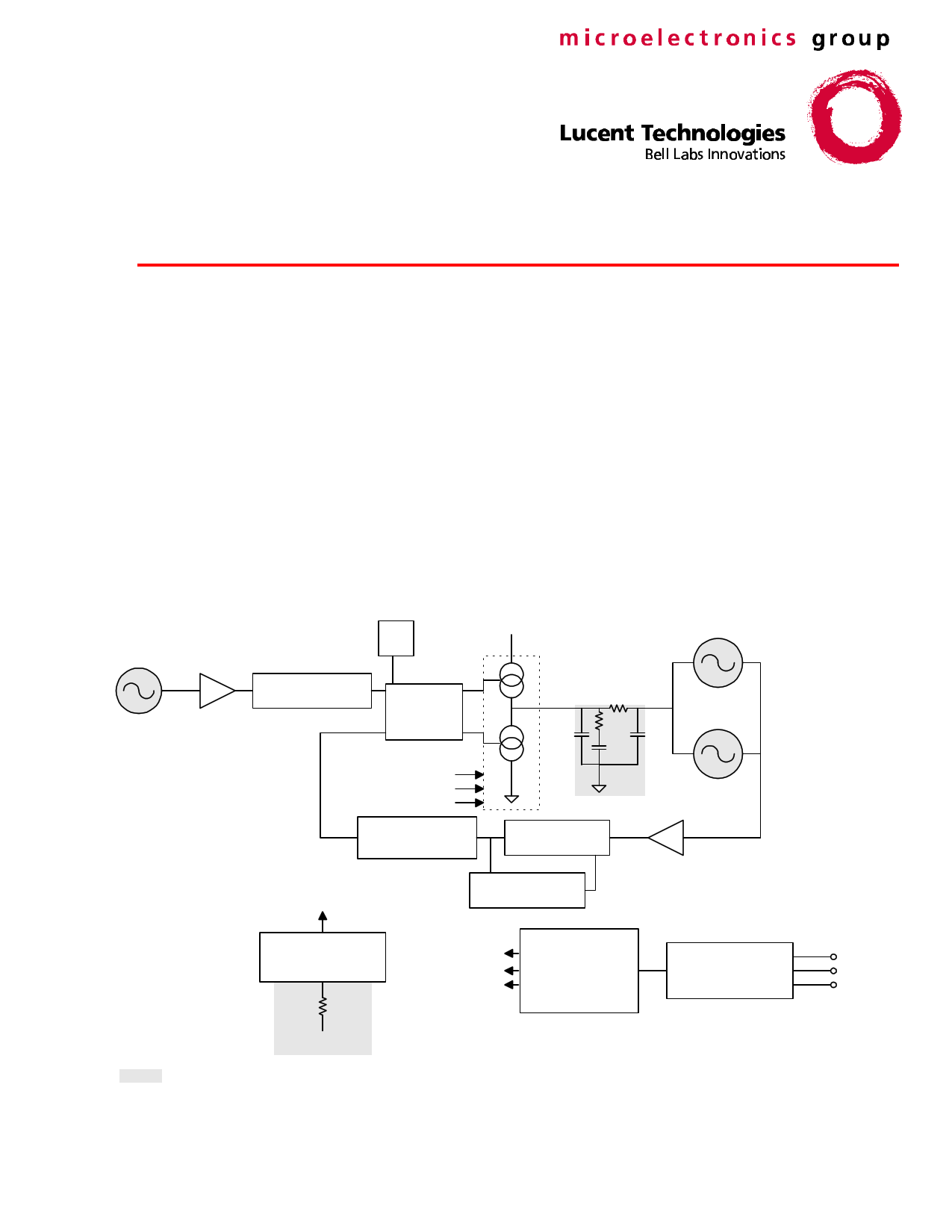
Figure 1. Block Diagram with Pinout
VCO BAND A
VCO BAND B
MAIN_IN
24-BIT SERIAL
SHIFT REGISTER
LAT
DAT
CLK
1 page 
Advance Data Sheet
December 1999
W3000 PLL Dual-Band Frequency Synthesizer
Absolute Maximum Ratings
Stresses in excess of the absolute maximum ratings can cause permanent damage to the device. These are
absolute stress ratings only. Functional operation of the device is not implied at these or any other conditions in
excess of those given in the operations sections of the data sheet. Exposure to absolute maximum ratings for
extended periods can adversely affect device reliability.
Parameter
Symbol
Min
Max Unit
Ambient Operating Temperature
Storage Temperature
Lead Temperature (soldering, 10 s)
Positive Supply Voltage
Positive Charge Pump Supply Voltage
Power Dissipation
ac Input Voltage
Digital Voltages
TA
Tstg
TL
VDD
VDDC
PD
—
—
–30
–65
—
0
0
—
0
Vss – 0.3
85
150
300
4.5
4.5
250
VDD
VDD + 0.3
°C
°C
°C
Vdc
Vdc
mW
Vp-p
Vdc
Electrostatic Discharge Caution
Although protection circuitry has been designed into this device, proper precautions should be taken to avoid
exposure to electrostatic discharge (ESD) during handling and mounting. Lucent Technologies Microelectronics
Group employs a human-body model (HBM) and a charged-device model (CDM) for ESD-susceptibility testing
and protection design evaluation. ESD voltage thresholds are dependent on the circuit parameters used to define
the model. No industry-wide standard has been adopted for CDM. However, a standard HBM (resistance =
1500 Ω, capacitance = 100 pF) is widely used and, therefore, can be used for comparison purposes.
Parameter
Model
Min
Max
Unit
ESD Threshold Voltage
HBM
1000
—
V
ESD Threshold Voltage (corner pins)
CDM
1000
—
V
ESD Threshold Voltage (noncorner pins) CDM
1500
—
V
Lucent Technologies Inc.
5
5 Page 
Advance Data Sheet
December 1999
W3000 PLL Dual-Band Frequency Synthesizer
REF Register
This section describes each bit of the reference register. The REF register is used for programming the division
ratio of the reference clock and for initial setup of the operation modes.
Table 7. REF Register Bit Description (C0 = 1, C1 = 0)
Bit
1
2:12
13
14
15:16
17
18:19
20
21
22
23
24
Name
C0 = 1
R[1:11]
D1
D2
D3, D4
D5
D6, D7
RE
ERES
EN1
LD
C1 = 0
Description
Register address bit. C0 = 1 for REF (last bit in serial sequence).
Reference frequency divide ratio.
Forced counter reload programming (synchronous/asynchronous).
Charge pump disable function.
Programable charge pump current for frequency band 2.
Phase detector polarity.
Programable charge pump current for frequency band 1.
Reset for first programming after powerup (1 = reset).
Enables external resistor (on RES pin) to set charge pump current.
Enable W3000. (0 is powerdown.)
Lock detect output enable.
Secondary address bit (first bit in serial sequence).
Table 8. REF Register
Last bit in serial sequence
First bit in serial sequence
1 2 3 4 5 6 7 8 9 10 11 12 13 14 15 16 17 18 19 20 21 22 23 24
C0 R R R R R R R R R R R D D D D D D D RE ERES EN LD C1
= 1 1 2 3 4 5 6 7 8 9 10 11 1 2 3 4 5 6 7
=0
Table 9. R1:R11: Reference Divider Ratio (Bits 2 to 12)
R11 R10 R9 R8 R7 R6 R5 R4 R3 R2 R1 Divide Ratio R
———————————
—*
00000000010
2
00000000011
3
...........
...........
...........
.
.
.
11111111111
2047
*The reference counter cannot operate with division numbers less than 2.
Lucent Technologies Inc.
11
11 Page | ||
| Páginas | Total 28 Páginas | |
| PDF Descargar | [ Datasheet W3000.PDF ] | |
Hoja de datos destacado
| Número de pieza | Descripción | Fabricantes |
| W3000 | W3000 PLL Dual-Band Frequency Synthesizer | Agere Systems |
| Número de pieza | Descripción | Fabricantes |
| SLA6805M | High Voltage 3 phase Motor Driver IC. |
Sanken |
| SDC1742 | 12- and 14-Bit Hybrid Synchro / Resolver-to-Digital Converters. |
Analog Devices |
|
DataSheet.es es una pagina web que funciona como un repositorio de manuales o hoja de datos de muchos de los productos más populares, |
| DataSheet.es | 2020 | Privacy Policy | Contacto | Buscar |