|
|
|
PDF 5358 Data sheet ( Hoja de datos )
| Número de pieza | 5358 | |
| Descripción | PHOTOELECTRIC SMOKE DETECTOR WITH INTERCONNECT AND TIMER | |
| Fabricantes | Allegro MicroSystems | |
| Logotipo | ||
Hay una vista previa y un enlace de descarga de 5358 (archivo pdf) en la parte inferior de esta página. Total 12 Páginas | ||
|
No Preview Available !
5358
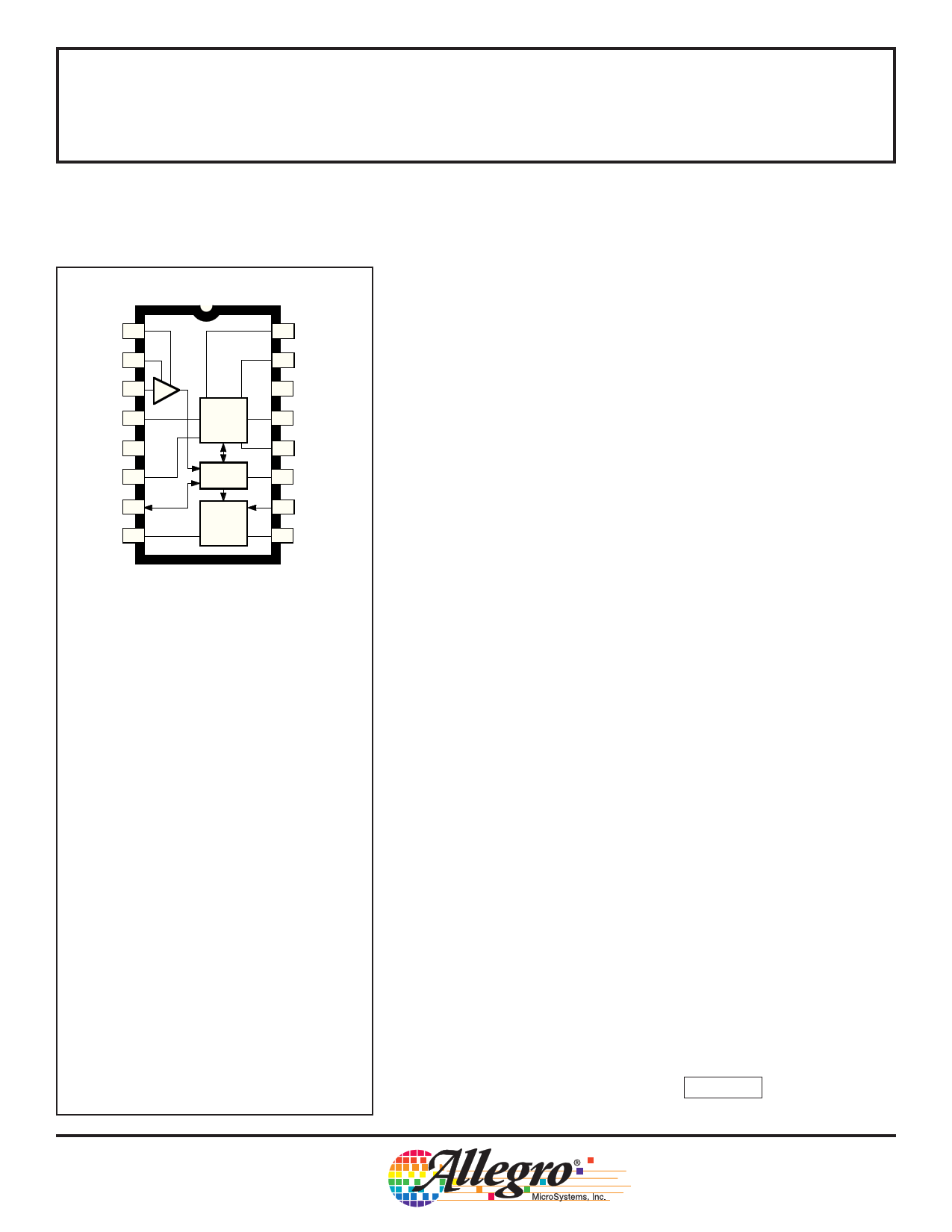
PHOTOELECTRIC SMOKE DETECTOR
WITH INTERCONNECT AND TIMER
C1 1
C2 2
DETECT 3
STROBE 4
+ SUPPLY 5 VDD
IRED 6
I/O 7
HORN1 8
16 TEST
15 HUSH
VSS 14 – SUPPLY
OSC. &
TIMING
13 TIMING RES.
12 OSC. CAP.
LOGIC
11 LED
HORN
DRIVER
10 FEEDBACK
9 HORN2
Dwg. PC-007
ABSOLUTE MAXIMUM RATINGS
(Voltages are referenced to VSS)
Supply Voltage Range,
VDD .................................... -0.5 V to +15 V
Input Voltage Range,
VIN ............................ -0.3 V to VDD + 0.3 V
Input Current, IIN ................................... 10 mA
Operating Temperature Range,
TA ..................................... -25°C to +75°C
Storage Temperature Range,
TS ................................... -55°C to +125°C
CAUTION: CMOS devices have input static
protection but are susceptible to damage if exposed
to extremely high static electrical charges.
The A5358CA is a low-current BiCMOS circuit providing all of the
required features for a photoelectric type smoke detector. This device
can be used in conjunction with an infrared photoelectric chamber to
sense scattered light from smoke particles. Special features are
incorporated in the design to facilitate calibration and testing of the
finished detector. The device is designed to comply with Underwriters
Laboratories Specification UL217 and British Standard BS 5446,
Part 1.
A variable-gain photo amplifier can be directly interfaced to an
infrared emitter/detector pair. The amplifier gain levels are determined
by two external capacitors that are then internally selected depending
on the operating mode. Low gain is selected during standby and timer
modes. During a local alarm this low gain is increased (internally) by
~10% to reduce false triggering. High gain is used during the push-
button test and during standby to periodically monitor the chamber
sensitivity.
The internal oscillator and timing circuitry keeps standby power to
a minimum by sensing for smoke every 10 seconds in a 10 µs window.
A special three-stage speedup sensing scheme is incorporated to
minimize the time to an audible alarm and also to reduce false trigger-
ing. Also, two consecutive cycles of degraded chamber sensitivity are
required for a warning signal to occur.
The A5358CA is supplied in a low-cost 16-pin dual in-line plastic
package. It is rated for continuous operation over the temperature
range of -25°C to +75°C.
FEATURES
s Interconnect Up to 50 Detectors
s Piezoelectric Horn Driver
s All Internal Low-Battery Detection
s Power-ON Reset
s Internal Timer & Control for Reduced Sensitivity
s Built-In Circuits to Reduce False Triggering
s 6 V to 12 V Operating Voltage Range
s ESD-Protection Circuitry on All Pins
Always order by complete part number: A5358CA .
1 page 
5358
PHOTOELECTRIC SMOKE DETECTOR
with INTERCONNECT and TIMER
AC ELECTRICAL CHARACTERISTICS, continued.
Characteristic
Strobe Pulse Period
Strobe Pulse Width
IRED Pulse Period
IRED Pulse Width
IRED Rise Time
IRED Fall Time
I/O to Active Delay
Rising Edge on I/O to Alarm
Horn Warning Pulse Period
Horn Warning Pulse Width
Horn ON Time
Horn OFF Time
Symbol
tst1
tst2
tst3
tst4
tst5
tst6
tw(st)
tired1
tired2
tired3
tired4
tired5
tired6
tw(ired)
tr(ired)
t f(ired)
td(io)
tr(io)
thorn
tw(horn)
ton(horn)
toff(horn)
Test Conditions
No Local or Remote Smoke
After 1 of 3 Valid Samples
After 2 of 3 Valid Samples
and During Local Alarm
Remote Alarm
Chamber Test or Low Supply
Test, No Local Alarm
Pushbutton Test, No Alarm
No Local or Remote Smoke
After 1 of 3 Valid Samples
After 2 of 3 Valid Samples
and During Local Alarm
Remote Alarm
Chamber Test, No Local Alarm
Pushbutton Test, No Alarm
10% to 90%
90% to 10%
Local Alarm
No Local Alarm
Low Supply and Degraded
Chamber Sensitivity
Low Supply and Degraded
Chamber Sensitivity
Local or Remote Alarm
Local or Remote Alarm
Test
Pin
4
4
4
4
4
4
4
6
6
6
6
6
6
6
6
6
7
7
8, 9
8, 9
8, 9
8, 9
VDD
9
9
9
9
9
9
9
9
9
9
9
9
9
9
9
9
9
9
9
9
* Limits over the operating temperature range are based on characterization data.
Characteristics are production tested at +25°C only.
Typical values are at +25°C and are given for circuit design information only.
Min.
9.6
2.42
1.21
Limits
Typ. Max.
– 11.9
2.70 2.96
1.34 1.47
Units
s
s
s
9.67 10.8 11.8
38.9 – 47.1
s
s
300 336 370 ms
9.5 – 11.5 ms
9.6
–
11.9
s
2.42 2.70 2.96
s
1.21 1.34 1.47
s
9.67 10.8 11.8
s
38.9
–
47.1
s
300 336 370 ms
94 – 116 µs
– – 30 µs
– – 200 µs
– 0 –s
–
–
1.34
s
38.9 – 47.1 s
9.5 – 11.5 ms
– 252 – ms
– 84 – ms
5 Page 
5358
PHOTOELECTRIC SMOKE DETECTOR
with INTERCONNECT and TIMER
16
0.280
0.240
Dimensions in Inches
(controlling dimensions)
9
0.014
0.008
0.430
MAX
0.300
BSC
1
0.070
0.045
0.210
MAX
0.015
MIN
0.022
0.014
16
7.11
6.10
0.775
0.735
0.100
BSC
8
0.005
MIN
0.150
0.115
Dimensions in Millimeters
(for reference only)
9
Dwg. MA-001-16A in
0.355
0.204
10.92
MAX
7.62
BSC
1
1.77
1.15
5.33
MAX
19.68
18.67
2.54
BSC
8
0.13
MIN
0.39
MIN
0.558
0.356
NOTES: 1. Lead thickness is measured at seating plane or below.
2. Lead spacing tolerance is non-cumulative.
3. Exact body and lead configuration at vendor’s option within limits shown.
3.81
2.93
Dwg. MA-001-16A mm
11 Page | ||
| Páginas | Total 12 Páginas | |
| PDF Descargar | [ Datasheet 5358.PDF ] | |
Hoja de datos destacado
| Número de pieza | Descripción | Fabricantes |
| 5350 | SMOKE DETECTOR WITH INTERCONNECT | Allegro MicroSystems |
| 5354 | SMOKE DETECTOR WITH INTERCONNECT | Allegro MicroSystems |
| 5355 | SMOKE DETECTOR WITH INTERCONNECT | Allegro MicroSystems |
| 5358 | PHOTOELECTRIC SMOKE DETECTOR WITH INTERCONNECT AND TIMER | Allegro MicroSystems |
| Número de pieza | Descripción | Fabricantes |
| SLA6805M | High Voltage 3 phase Motor Driver IC. |
Sanken |
| SDC1742 | 12- and 14-Bit Hybrid Synchro / Resolver-to-Digital Converters. |
Analog Devices |
|
DataSheet.es es una pagina web que funciona como un repositorio de manuales o hoja de datos de muchos de los productos más populares, |
| DataSheet.es | 2020 | Privacy Policy | Contacto | Buscar |