|
|
|
PDF NGTB20N135IHRWG Data sheet ( Hoja de datos )
| Número de pieza | NGTB20N135IHRWG | |
| Descripción | IGBT | |
| Fabricantes | ON Semiconductor | |
| Logotipo | ||
Hay una vista previa y un enlace de descarga de NGTB20N135IHRWG (archivo pdf) en la parte inferior de esta página. Total 10 Páginas | ||
|
No Preview Available !
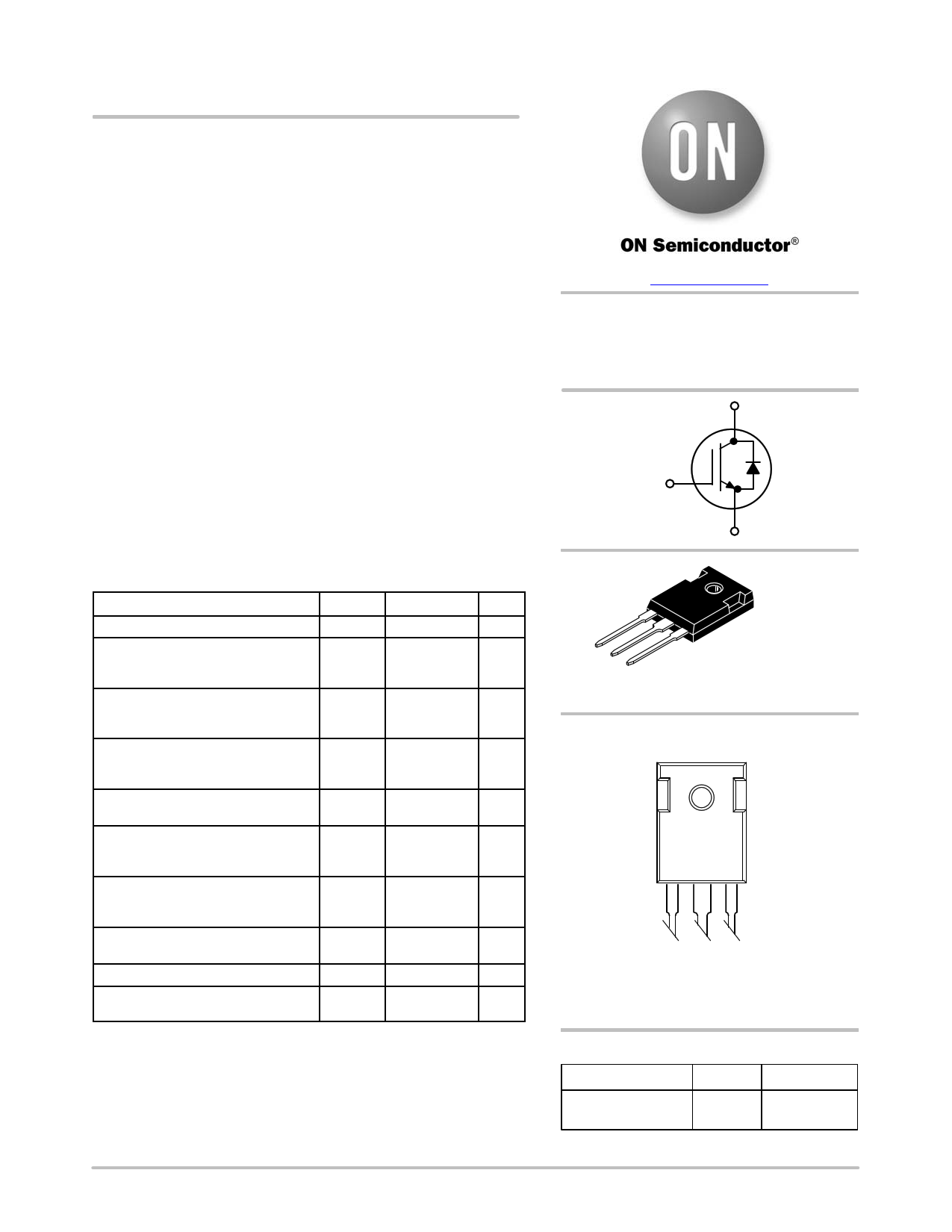
NGTB20N135IHRWG
IGBT with Monolithic Free
Wheeling Diode
This Insulated Gate Bipolar Transistor (IGBT) features a robust and
cost effective Field Stop (FS) Trench construction, and provides
superior performance in demanding switching applications, offering
both low on−state voltage and minimal switching loss. The IGBT is
well suited for resonant or soft switching applications.
Features
• Extremely Efficient Trench with Fieldstop Technology
• 1350 V Breakdown Voltage
• Optimized for Low Losses in IH Cooker Application
• Reliable and Cost Effective Single Die Solution
• These are Pb−Free Devices
Typical Applications
• Inductive Heating
• Consumer Appliances
• Soft Switching
ABSOLUTE MAXIMUM RATINGS
Rating
Symbol
Value
Unit
Collector−emitter voltage
Collector current
@ TC = 25°C
@ TC = 100°C
VCES
IC
1350
40
20
V
A
Pulsed collector current, Tpulse
limited by TJmax, 10 ms Pulse,
VGE = 15 V
Diode forward current
@ TC = 25°C
@ TC = 100°C
ICM 120 A
IF A
40
20
Diode pulsed current, Tpulse limited
by TJmax, 10 ms Pulse, VGE = 0 V
Gate−emitter voltage
Transient Gate−emitter Voltage
(Tpulse = 5 ms, D < 0.10)
Power Dissipation
@ TC = 25°C
@ TC = 100°C
IFM
VGE
PD
120
$20
±25
394
197
A
V
W
Operating junction temperature
range
TJ −40 to +175 °C
Storage temperature range
Lead temperature for soldering, 1/8”
from case for 5 seconds
Tstg
TSLD
−55 to +175
260
°C
°C
Stresses exceeding those listed in the Maximum Ratings table may damage the
device. If any of these limits are exceeded, device functionality should not be
assumed, damage may occur and reliability may be affected.
www.onsemi.com
20 A, 1350 V
VCEsat = 2.20 V
Eoff = 0.60 mJ
C
G
E
G
C
E
TO−247
CASE 340AL
MARKING DIAGRAM
20N135IHR
AYWWG
A = Assembly Location
Y = Year
WW = Work Week
G = Pb−Free Package
ORDERING INFORMATION
Device
Package Shipping
NGTB20N135IHRWG TO−247 30 Units / Rail
(Pb−Free)
© Semiconductor Components Industries, LLC, 2017
March, 2017 − Rev. 1
1
Publication Order Number:
NGTB20N135IHR/D
1 page 
NGTB20N135IHRWG
TYPICAL CHARACTERISTICS
1.8
1.6
1.4
1.2
1
0.8
0.6
0.4
0.2
0
5
10000
Eoff
1000
td(off)
tf
VCE = 600 V
VGE = 15 V
TJ = 150°C
IC = 20 A
15 25 35 45 55 65 75 85
RG, GATE RESISTOR (W)
Figure 13. Switching Loss vs. Rg
100
VCE = 600 V
VGE = 15 V
TJ = 150°C
IC = 20 A
10
5 15 25 35 45 55 65 75
RG, GATE RESISTOR (W)
Figure 14. Switching Time vs. Rg
85
1.8
1.6
1.4 Eoff
1.2
1
0.8
0.6 IC = 20 A
0.4 VGE = 15 V
TJ = 150°C
0.2 Rg = 10 W
0
250 300 350 400 450 500 550 600 650 700 750 800
VCE, COLLECTOR−EMITTER VOLTAGE (V)
Figure 15. Switching Loss vs. VCE
1000
td(off)
tf
100
IC = 20 A
VGE = 15 V
TJ = 150°C
Rg = 10 W
10
250 300 350 400 450 500 550 600 650 700 750 800
VCE, COLLECTOR−EMITTER VOLTAGE (V)
Figure 16. Switching Time vs. VCE
1000
100
10
1 ms 100 ms
dc operation
50 ms
1000
VGE = 15 V, TC = 125°C
100
1
Single Nonrepetitive
Pulse TC = 25°C
0.1 Curves must be derated
linearly with increase
in temperature
0.01
1 10
100
1000
VCE, COLLECTOR−EMITTER VOLTAGE (V)
Figure 17. Safe Operating Area
10
1
1 10 100 1000
VCE, COLLECTOR−EMITTER VOLTAGE (V)
Figure 18. Reverse Bias Safe Operating Area
www.onsemi.com
5
5 Page | ||
| Páginas | Total 10 Páginas | |
| PDF Descargar | [ Datasheet NGTB20N135IHRWG.PDF ] | |
Hoja de datos destacado
| Número de pieza | Descripción | Fabricantes |
| NGTB20N135IHRWG | IGBT | ON Semiconductor |
| Número de pieza | Descripción | Fabricantes |
| SLA6805M | High Voltage 3 phase Motor Driver IC. |
Sanken |
| SDC1742 | 12- and 14-Bit Hybrid Synchro / Resolver-to-Digital Converters. |
Analog Devices |
|
DataSheet.es es una pagina web que funciona como un repositorio de manuales o hoja de datos de muchos de los productos más populares, |
| DataSheet.es | 2020 | Privacy Policy | Contacto | Buscar |