|
|
|
PDF ACT413 Data sheet ( Hoja de datos )
| Número de pieza | ACT413 | |
| Descripción | Quasi-Resonant PWM Controller | |
| Fabricantes | Active-Semi | |
| Logotipo | ||
Hay una vista previa y un enlace de descarga de ACT413 (archivo pdf) en la parte inferior de esta página. Total 16 Páginas | ||
|
No Preview Available !
ACT413
Rev 2, 27-Feb-14
ActivePSRTM Quasi-Resonant PWM Controller
FEATURES
• Patented Primary Side Regulation
Technology
• Quasi-Resonant Operation
• Adjustable up to 85kHz Switching Frequency
• +/-5% Output Voltage Regulation
• Accurate OCP/OLP Protection
• Integrated Output Cord Compensation
• Integrated Line and Primary Inductance
Compensation
• Built-in Soft-Start Circuit
• Line Under-Voltage, Thermal, Output Over-
voltage, Output Short Protections
• Current Sense Resistor Short Protection
• Transformer Short Winding Protection
• Less than 100mW Standby Power
• Complies with Global Energy Efficiency and
CEC Average Efficiency Standards
• Tiny SOT23-6 Packages
mode including cycle-by-cycle current limiting.
ACT413 is to achieve no overshoot and very short
rise time even with big capacitive load (4000µF)
with the built-in fast and soft start process, .
The Quasi-Resonant (QR) operation mode can
effectively improve efficiency, reduce the EMI noise
and further reduce the components in input filter.
ACT413 is idea for application up to 36 Watt.
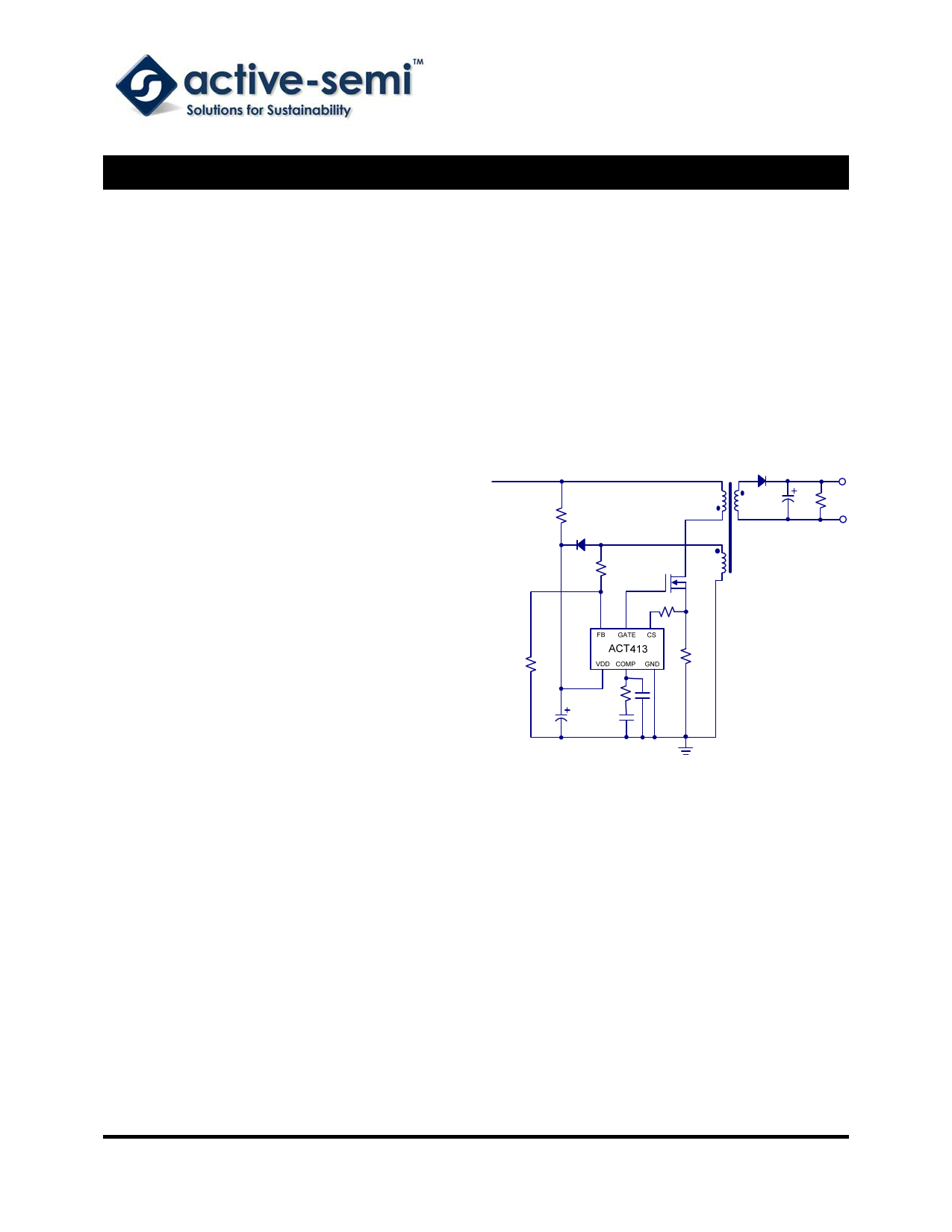
Figure 1:
Simplified Application Circuit
APPLICATIONS
• AC/DC Adaptors/Chargers for Smart Phones,
iPADs, ADSL, PDAs, E-books
• Adaptors for Portable Media Player, DSCs,
and Other
GENERAL DESCRIPTION
The ACT413 is a high performance peak current
mode PWM controller which applies ActivePSRTM
and ActiveQRTM technology. ACT413 achieves
accurate voltage regulation without the need of an
opto-coupler or reference device.
The ACT413 is designed to achieve less than
100mW Standby Power. By applying frequency fold
back and ActiveQRTM technology, ACT413
exceeds the latest ES2.0 efficiency standard.
ACT413 integrates comprehensive protection. In
case of over temperature, over voltage, short
winding, short current sense resistor, open loop
and overload conditions, it would enter auto restart
Innovative PowerTM
-1-
Active-Semi Proprietary―For Authorized Recipients and Customers
ActivePSRTM is a trademark of Active-Semi.
www.active-semi.com
Copyright © 2014 Active-Semi, Inc.
1 page 
ACT413
Rev 2, 27-Feb-14
ELECTRICAL CHARACTERISTICS CONT’D
VDD = 13V, LM = 0.6mH, RCS = 1.15Ω, VOUT = 5V, NP = 102, NS = 7, NA = 17, TA = 25°C, unless otherwise specified,5V2.4A application.)
PARAMETER
Protection
CS Short Waiting Time
CS Short Detection Threshold
CS Open Threshold Voltage
Abnormal OCP Blanking Time
Inductance Short CS Threshold Voltage
Thermal Shutdown Temperature
Thermal Hysteresis
Line UVLO
Line UVLO Hysteresis
Line OVP
VFB Over Voltage Protection
Valley Detection
Valley Detection Time Window
SYMBOL TEST CONDITIONS
IFBUVLO
IFBOVP
VCOMP = 0.45V
MIN
2
TYP MAX UNIT
2.25 3
µs
0.1 0.15
V
1.75 V
190 ns
1.75 V
135 ˚C
20 ˚C
0.2 mA
20 µA
2.4 mA
3V
3.3 µs
Innovative PowerTM
-5-
Active-Semi Proprietary―For Authorized Recipients and Customers
ActivePSRTM is a trademark of Active-Semi.
www.active-semi.com
Copyright © 2014 Active-Semi, Inc.
5 Page 
ACT413
Rev 2, 27-Feb-14
TYPICAL APPLICATION CONT’D
An EE16 core is selected for the transformer. From
the manufacture’s catalogue recommendation, the
gapped core with an effective inductance ALE of 58
nH/T2 is selected. The turn of the primary winding
is:
NP =
LP =
ALE
0 .6 mH
58 nH / T 2
= 102 T
(13)
The turns of secondary and auxiliary winding can
be derived accordingly:
NS
=
Ns
Np
× Np
=1
13.64
×102
≈ 7T
(14)
NA
=
NA
NS
× Ns
=
2.47 ×7
≈ 17T
(15)
Determining the value of the current sense resistor
(R9) uses the peak current in the design. Since the
ACT413 internal current limit is set to 1V, the
design of the current sense resistor is given by:
RCS =
=
VCS
2 × IOUT _ OCP × VOUT
LP × FSW η× system
1
2×3×5
≈ 1.15 .Ω
(16)
0.6 mH × 80 kHz × 0.8
Two 820µF electrolytic capacitors are used to keep
the ripple small.
PCB Layout Guideline
Good PCB layout is critical to have optimal
performance. Decoupling capacitor (C4) and
feedback resistor (R5/R6) should be placed close to
VDD and FB pin respectively. There are two main
power path loops. One is formed by C1/C2, primary
winding, Mosfet transistor and current sense
resistor (R9). The other is secondary winding,
rectifier D4 and output capacitors (C7/C6). Keep
these loop areas as small as possible. Connecting
high current ground returns, the input capacitor
ground lead, and the ACT413 GND pin to a single
point (star ground configuration).
The voltage feedback resistors are selected
according to the Ioccmax and Vo. The design
Io_cc max is given by:
fs
=
Np
Ns
×
R fb1 × R fb 2
R fb1 + R fb 2
×
Lp
VO + VD
×
V cs
R cs
× K f _ sw
(17)
The design Vo is given by:
Vo
= (1 +
Rfb1
R fb 2
)× Ns
Na
× VFB
− VD
(18)
Where k is IC constant and K=0.000022, then we
can get the value:
Rfb1 = 68K ,Rfb2 = 11.5K
(19)
When selecting the output capacitor, a low ESR
electrolytic capacitor is recommended to minimize
ripple from the current ripple. The approximate
equation for the output capacitance value is given
by:
C = f ×I VOUT
OUT
sw RIPPLE
= 2.4
80 k × 50 mV
= 600 μF
(20)
Innovative PowerTM
- 11 -
Active-Semi Proprietary―For Authorized Recipients and Customers
ActivePSRTM is a trademark of Active-Semi.
www.active-semi.com
Copyright © 2014 Active-Semi, Inc.
11 Page | ||
| Páginas | Total 16 Páginas | |
| PDF Descargar | [ Datasheet ACT413.PDF ] | |
Hoja de datos destacado
| Número de pieza | Descripción | Fabricantes |
| ACT410 | Quasi-Resonant PWM Controller | Active-Semi |
| ACT411 | Quasi-Resonant PWM Controller | Active-Semi |
| ACT412 | Quasi-Resonant PWM Controller | Active-Semi |
| ACT413 | Quasi-Resonant PWM Controller | Active-Semi |
| Número de pieza | Descripción | Fabricantes |
| SLA6805M | High Voltage 3 phase Motor Driver IC. |
Sanken |
| SDC1742 | 12- and 14-Bit Hybrid Synchro / Resolver-to-Digital Converters. |
Analog Devices |
|
DataSheet.es es una pagina web que funciona como un repositorio de manuales o hoja de datos de muchos de los productos más populares, |
| DataSheet.es | 2020 | Privacy Policy | Contacto | Buscar |