|
|
|
PDF CH1786 Data sheet ( Hoja de datos )
| Número de pieza | CH1786 | |
| Descripción | CH1786 Family of Ultra Small 2400bps Modems | |
| Fabricantes | ETC | |
| Logotipo | ||
Hay una vista previa y un enlace de descarga de CH1786 (archivo pdf) en la parte inferior de esta página. Total 18 Páginas | ||
|
No Preview Available !
CH1786 Family of Ultra Small 2400bps Modems
INTRODUCTION
The CH1786 family of modems are a full function,
FCC Part 68 approved 2400bps modem. These
modems provide a fast, easy and flexible way to
integrate a modem into any OEM product while
utilizing the minimum amount of PCB space (1.01 ”x
1.27 ”x 0.52 ”). The CH1786 family only requires two
external interfaces: a CCITT V.24 serial interface that
can be routed directly to a UART, and a Tip and Ring
interface which goes directly to an RJ-11 jack for the
PSTN line connection. The CH1786 can be
controlled with industry standard AT commands and,
hence, is compatible with available industry
communication software.
All CH1786 modems support asynchronous operation
at 2400bps, 1200bps, and 300bps to both Bell and
CCITT standards. The resident PSTN line interface,
or Data Access Arrangement (DAA), while being FCC
approved, is also Canadian DOT approvable and can
be approved in other countries that require 1500VAC
RMS isolation requirements per UL 1950 Edition 3.
The CH1786 family of modems operate off a single 5-
volt supply. The low power operation and automatic
standby mode make these modems ideally suited for
portable equipment. In addition, their small physical
size affords maximum flexibility in equipment design.
FEATURES
• Supports Standards
212,and Bell 103
CCITT
V.22bis,V.22,Bell
• FCC Part 68 approved and DOT CSA CS-03 Part I
approvable
• UL 1950 and CSA C22.2 950 Listed
• UL File Number: E104957
• AT Command structure with extensions
• 1500 VAC RMS isolation barrier minimum, 2122V
peak surge protection minimum
• Single 5 volt operation
• Low power operation with automatic reduced power
standby mode
• Automatic adaptive and fixed compromise
equalization
• Size: 1.01 ”x 1.27 ”x 0.52 ”(nominal)
• NVRAM allows storage of custom configurations
and telephone numbers
CH1786 FAMILY
CH1786
NVRAM, Voice/ Inject,
Operating Temperature:
0°C to +70°C
Hermetic,
CH1786ET
NVRAM, Voice/ Inject, Hermetic,
Operating Temperature:
-40°C to +85°C
CH1786NH
Non-Hermetic, Operating
Temperature:
0°C to +70°C
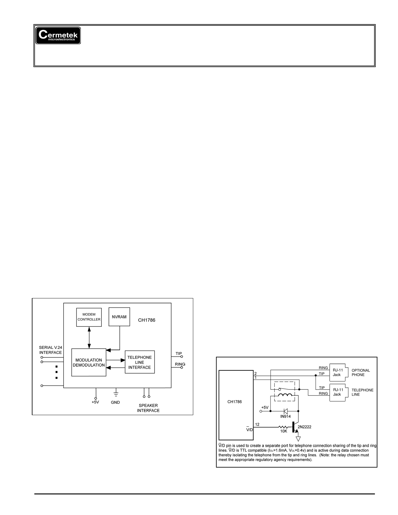
Figure 1. Functional Block Diagram of CH1786.
The CH1786 comes with FCC Part 68 approval and is
shipped from the factory with an FCC Part 68 label
indicating the registration number and ringer
equivalent. This label should be prominently
displayed on the end product.
Figure 2. Voice/ Data Port Control
2003 Cermetek Microelectronics, Inc.
Page 1
Document No. 607-0004 Revision L1 (06/03)
1 page 
Cermetek Microelectronics, Inc.
Reset. Upon applying power to the CH1786, the
CH1786 automatically generates an internal reset
pulse. The user may also reset the modem externally
by applying a high-going reset pulse to the RST pin
for at least 10ms after the +5V power supply has
stabilized. Delay sending commands to CH1786 for
200ms after reset has been initiated to allow the
CH1786 time to properly reconfigure.
Training the Modem. Each modem must be trained
to match its host’s speed and parity so that it is able
to recognize serial asynchronous commands sent to it
by the host’s is UART. The host must retrain the
modem each time a reset pulse is applied on RST or
after a RESET serial command has been issued.
Modem Training Command Sequence. The
CH1786 is trained by sending it the following
sequence:
Enter: AT<CR>
Result: OK
Where: A and T may be either upper or lower case
but must be the same case.
<CR> represents carriage return
The AT sequence is referred to as an attention
sequence. The CH1786 will respond with one of the
following status messages, depending on whether it
is optioned for Terse (abbreviated) or Verbose
(English) status messages.
Result: 0<CR> (Terse)
or
Result: <CR><LF>OK<CR><LF> (Verbose)
Where: <CR> represents carriage return (ASCII 13
or HEX 0D).
<LF> represents line feed (ASCII 10 or
HEX 0A).
After responding with an OK, the CH1786 is in idle
mode and is ready to accept additional commands.
An alternate attention sequence A/ may be sent
which behaves much like the AT sequence except
that it causes the previously entered command
specified with an AT prefix to be executed. When
given, both the AT and A/ must be in upper case
ASCII. No carriage return is needed for the A/
command.
THE COMMAND FORMAT
Typical commands consist of three elements: the
attention sequence, the commands themselves, and
a terminating carriage return.
AT[commands]<CR>.
Where: AT represents attention sequence.
[Commands] represents command strings.
CH1786 Family of Ultra Small 2400bps Modems
<CR> represents carriage return (ASCII 13
or HEX 0D).
When entering commands to the modem, the
backspace character-control-H (ASCII 8 or HEX 08)
may be used to edit mistakes. AT and A/ may not be
edited. Multiple commands may be placed in the
command line. A command line may be as long as
40 characters, excluding the letters AT. By way of
example, the command below instructs the CH1786
to configure itself to not echo characters when in
command mode E0 and then put itself in answer
mode A.
Enter: ATE0A<CR>
Result: OK
AT Command Set. The available command set is
divided into four types of commands: dial modifiers,
basic commands, ampersand and percent
commands. Refer to the complete list in Table 5.
AT Command Data Rate. With the serial interface,
the rate is speed sensed for parity and format.
THE STATUS MESSAGES
The CH1786 responds with a status message after
each command is executed. This status message
may either be a single digit followed by a carriage
return or a carriage return and line feed with a
message in English, followed by a carriage return and
line feed.
The basic status code subsets are enabled with the
Xn command. Where n=0,1,2,3,4 establishes the
result codes allowed by the user.
X0: Result Codes 0, 1, 2, 3, 4 allowed
X1: Result Codes 0, 1, 2, 3, 4, 5, 10 allowed
X2: Result Codes 0,1, 2, 3, 4, 5, 6, 10 allowed
X3: Result Codes 0, 1, 2, 3, 4, 5, 7, 10 allowed
X4: Result Codes 0, 1, 2, 3, 4, 5, 6, 7, 10 allowed.
NOTE
The CH1786 is factory set to X4, which allows all
result codes.
MODEM STATES
The CH1786 can be in either command mode or data
mode. When the modem is idle, it is in command
mode by default and will recognize commands.
When data transmission is in progress, the CH1786 is
in the data mode state and will not recognize
commands. To force the CH1786 to recognize
commands, the host must send an escape sequence
to the CH1786 forcing it out of data mode and into
command mode.
2003 Cermetek Microelectronics, Inc.
Page 5
Document No. 607-0004 Revision L1 (06/03)
5 Page 
Cermetek Microelectronics, Inc.
2. The circuitry from the CH1786 to the telephone
line interface must be provided in wiring that
carries no other circuitry other than that
specifically allowed in the FCC rules (such as A
and A1 leads).
3. Connection to phone line should be made
through an RJ-11C jack.
4. PCB traces from the modem’s RING and TIP pins
to the RJ-11C jack must be 0.1 inch spacing or
greater to one another and 0.2 inch spacing or
greater to all other traces. The traces should
have a nominal width of 0.020 inches or greater.
5. The RING and TIP PCB traces should be as
short as possible and oriented to prevent
coupling other high speed or high frequency
signals present on the host circuit PCB.
6. No additional circuitry other than that shown in
Figure 7A or 7B may be connected between the
modem module and the RJ-11C jack. Doing so
will invalidate the FCC approval.
7. The CH1786LC, CH1786LCNE, and CH1786NH
(only) requires external surge protection (see
Figure 7B). This is mandatory to maintain FCC
Part 68 conveyed approval.
8. The CH1786, the RJ-11C jack, the interfacing
circuitry and all PCB traces in between, must be
contained on a PCB with a 94 V-0 flammability
rating.
9. The supplied FCC registration label must be
applied visibly on the outside of the product.
10. The product’s User Manual must provide the user
with instructions for connection and use as
recommended in the FCC Registration Section
below.
CH1786 Family of Ultra Small 2400bps Modems
CH1786 HANDLING AND ASSEMBLY
RECOMMENDATIONS
The CH1786 contains static-sensitive components
and should only be handled by personnel and in
areas that are properly protected against static
discharge. The two recommended mounting
techniques for physically connecting the CH1786 to a
PCB are discussed below.
Direct Soldering. The CH1786 may be wave
soldered. All CH1786 products are hermetically
sealed (except the CH1786LCNE, CH1786NE, and
CH1786NH) and will not be harmed by industry
standard wave soldering processes. Cermetek
recommends against exposing the non-hermetic
CH1786LCNE, CH1786NE, and CH1786NH to
aqueous based rinsing processes.
Socketing. The socketing approach to mounting
eliminates cleaning and desoldering concerns. When
the socket is used, it must make a solid connection to
all pins. Failure to do so will cause unreliable or
intermittent operation. Also, steps should be taken to
assure that the module remains tightly seated in the
socket during shipping. Cermetek recommends using
sockets from Samtec. See Application Note # 130,
Summary of Recommended Suppliers.
FCC REGISTRATION
All products in the CH1786 family are registered with
the FCC (Federal Communications Commission)
under Part 68. To maintain the validity of the
registration, you must serve notice to the end user of
the products of several restrictions the FCC places on
the modem and its use.
In addition to restriction notification, the FCC requires
that Cermetek make all repairs to all products in the
CH1786 family. If repairs are necessary after
installation of the CH1786 in the end product and the
end product has been delivered to the end user, the
end product must be returned to the end product
supplier where the CH1786 can be removed and then
forward to Cermetek for repair. The following notice
is recommended and should be included in the end
product’s user manual.
Figure 6. Speaker Control Circuit: Optional to
allow for call progress monitoring.
2003 Cermetek Microelectronics, Inc.
FOR YOUR USER’S MANUAL
The FCC Part 68 rules require the following (or
equivalent) be provided to the end user of equipment
containing a DAA.
Type of Service. The (insert end product name) is
designed to be used on standard device telephone
lines. It connects tot he telephone line by means of a
standard jack called the USOC RJ-11C (or USOC
RJ45S). Connection to telephone-company-provided
coin service (central office implemented systems) is
Page 11
Document No. 607-0004 Revision L1 (06/03)
11 Page | ||
| Páginas | Total 18 Páginas | |
| PDF Descargar | [ Datasheet CH1786.PDF ] | |
Hoja de datos destacado
| Número de pieza | Descripción | Fabricantes |
| CH1786 | CH1786 Family of Ultra Small 2400bps Modems | ETC |
| Número de pieza | Descripción | Fabricantes |
| SLA6805M | High Voltage 3 phase Motor Driver IC. |
Sanken |
| SDC1742 | 12- and 14-Bit Hybrid Synchro / Resolver-to-Digital Converters. |
Analog Devices |
|
DataSheet.es es una pagina web que funciona como un repositorio de manuales o hoja de datos de muchos de los productos más populares, |
| DataSheet.es | 2020 | Privacy Policy | Contacto | Buscar |